Localization by learning of wave-signal distributions

a wave-signal distribution and localization technology, applied in the direction of navigation instruments, programs, instruments, etc., can solve the problems of inability to implement, lack of resources necessary for running known systems, and inability to effectively take into account practical effects, etc., and achieve the effect of less accura

Active Publication Date: 2015-01-06
IROBOT CORP
View PDF1441 Cites 37 Cited by
  • Summary
  • Abstract
  • Description
  • Claims
  • Application Information

AI Technical Summary

Benefits of technology

[0007]A method for accurately estimating the pose of a mobile object in an environment, without an a priori map of that environment, is disclosed. The method generates the estimates in near real-time, compensates for the rotational variability of a signal sensor, compensates for signal multipath effects, and is statistically more accurate than relying on dead reckoning or signal detection alone. The method comprises decomposing an environment to be navigated by the mobile object into two or more cells, each of which is defined by three or more nodes. An expected measure of a background signal is determined for each of the nodes, and an expected measure of the signal at positions interior to the cell is estimated based on the expected measure at each of two or more of the cell's nodes. The actual or expected measures at the nodes need not be known a priori, because as the mobile object navigates the environment, the mobile object maps the signal measure at substantially the same time as it localizes by using, for example, an appropriate implementation of an appropriate SLAM algorithm. During an initialization process, initial values for some or all of the calibration parameters including but not limited to the rotational variability, sensor error, and the like, are optionally determined. Also obtained is a scale parameter that correlates a position or location to an expected signal measure. The initialization process makes use of data from the signal sensor as well as a motion sensor and allows for initial determination of an expected signal measure at each of the nodes of a cell. During the SLAM phase, the pose of the mobile object is estimated based on some or all of the following: data from the motion sensor, data from the signal sensor, a map of expected signal measures, the calibration parameters, and previous values for these items. If the mobile object leaves a cell defined by initialized nodes, then the initialization process may be rerun to initialize any previously uninitialized nodes of the cell the mobile object enters. Optionally, some or all of the uninitialized nodes of the cell the mobile object enters are initialized by extrapolating from nodes of cells neighboring the entered cell.
[0009]During an initialization process, initial values for some or all of the calibration parameters, including but not limited to rotational variability, sensor error, and the like, are optionally determined. Also obtained is a scale parameter that correlates a position to an expected signal measure. The scale parameter may become less accurate for positions (locations) not proximate to the cell or the nodes of the cell. The initialization process makes use of data from the signal sensor as well as a motion sensor and allows for initial determination of the expected signal measure at each of the nodes of a cell.

Problems solved by technology

However, many mobile devices lack the resources necessary to run known systems themselves or are unable to implement them while performing additional tasks, and many such systems fail to effectively take into account practical issues such as manufacturing and production variances, variability of the surfaces of the area in which a mobile device operates (such as uneven terrain or floors), and complications resulting from signal interaction with environmental features such as walls or trees.
The scale parameter may become less accurate for positions (locations) not proximate to the cell or the nodes of the cell.

Method used


Image

  • Localization by learning of wave-signal distributions
  • Localization by learning of wave-signal distributions
  • Localization by learning of wave-signal distributions

Examples


Embodiment Construction

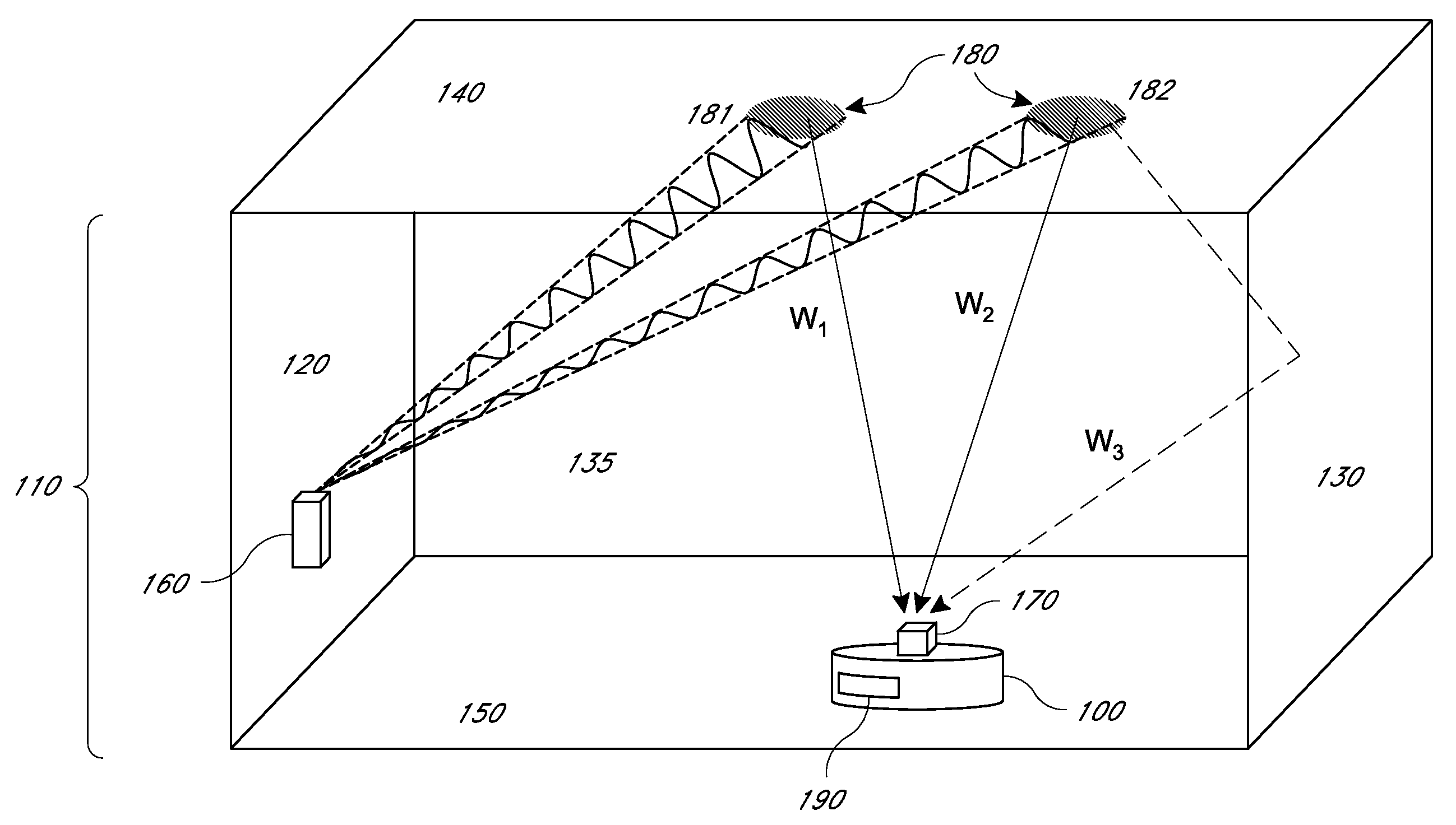
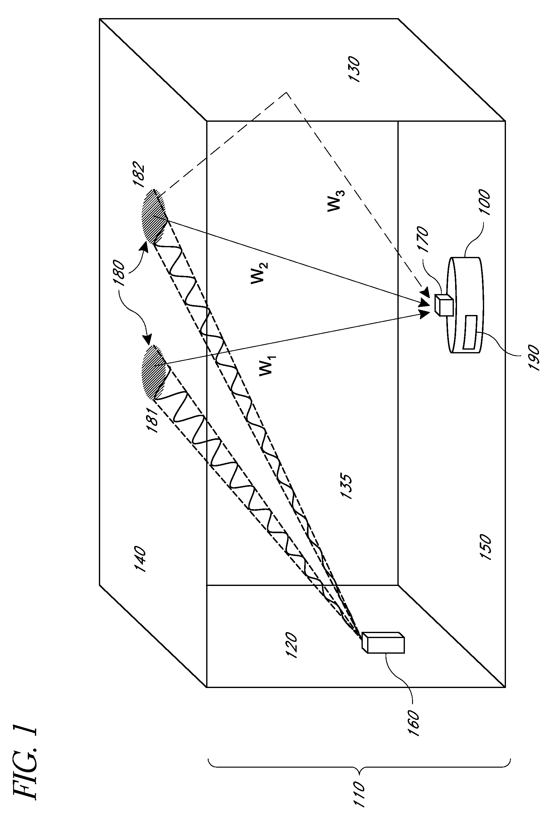
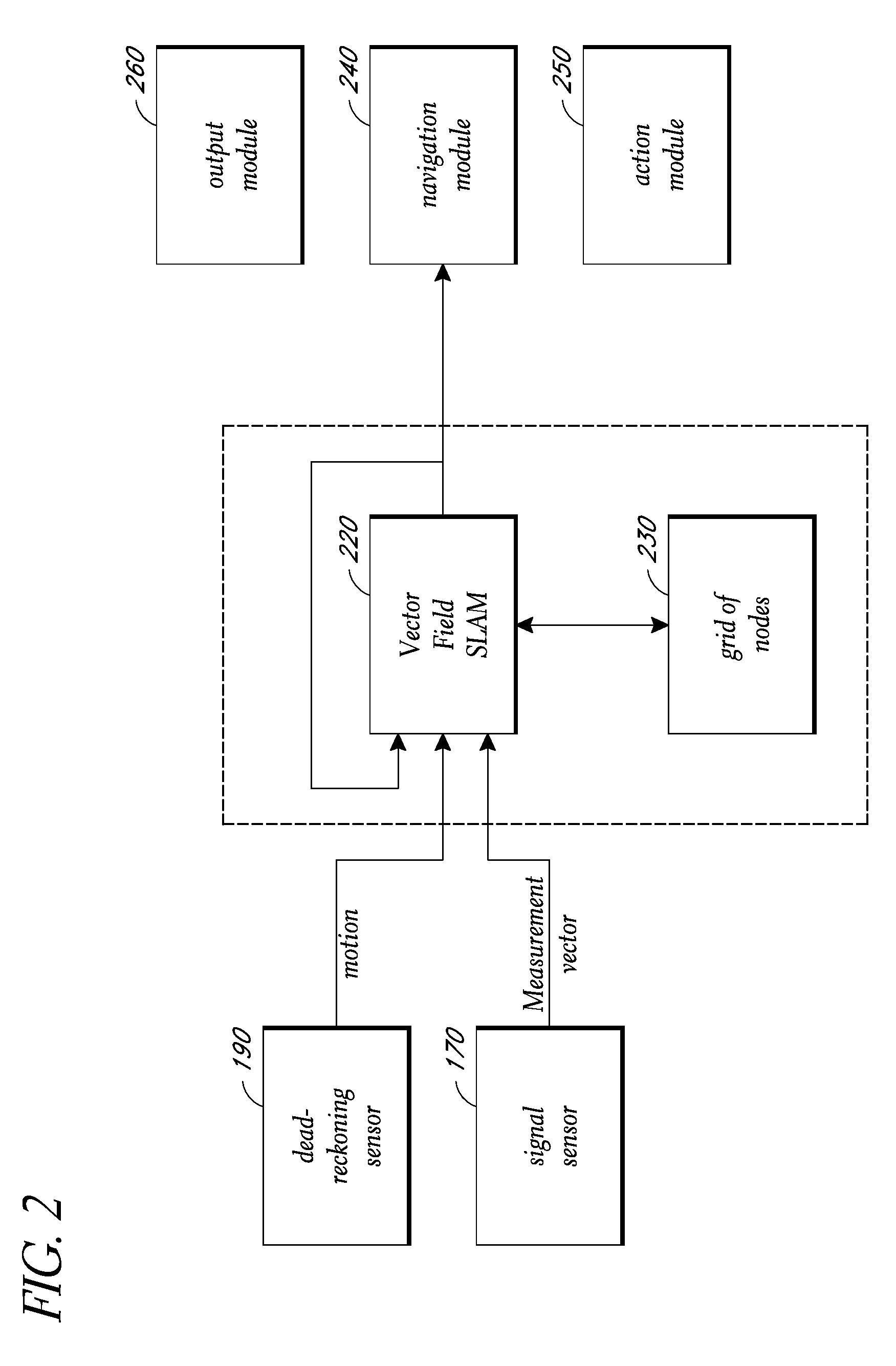
[0033]Described herein are methods and systems for the localization of an object, such as a mobile object (e.g., a robotic floor cleaner). Certain embodiments may utilize such mobile object localization to navigate the mobile object. By way of illustration and not limitation, the mobile object may optionally be an autonomous, semiautonomous, or remotely directed floor cleaner (e.g., a sweeper, a vacuum, and / or a mopper), delivery vehicle (e.g., that delivers mail in a building, food in a hospital or dormitory, etc.), or monitoring vehicle (e.g., pollution or contaminant detector, security monitor), equipped with one or more drive motors which drive one or more wheels, tracks, or other such device, where the drive motors may be under control of a computing device executing a program stored in non-transitory memory (e.g., it persists when the object is powered down or when some other data is overwritten or erased).

[0034]Example embodiments will now be described with reference to certa...


PUM


Abstract

A robot having a signal sensor configured to measure a signal, a motion sensor configured to measure a relative change in pose, a local correlation component configured to correlate the signal with the position and / or orientation of the robot in a local region including the robot's current position, and a localization component configured to apply a filter to estimate the position and optionally the orientation of the robot based at least on a location reported by the motion sensor, a signal detected by the signal sensor, and the signal predicted by the local correlation component. The local correlation component and / or the localization component may take into account rotational variability of the signal sensor and other parameters related to time and pose dependent variability in how the signal and motion sensor perform. Each estimated pose may be used to formulate new or updated navigational or operational instructions for the robot.

Description

CROSS-REFERENCE TO RELATED APPLICATIONS[0001]This application claims the benefit under 35 U.S.C. §119(e) of U.S. Provisional Application No. 61 / 280,677, filed Nov. 6, 2009, the entirety of which is hereby incorporated by reference.BACKGROUND[0002]1. Field of Endeavor[0003]What is disclosed herein relates to determining the position and orientation of an object.[0004]2. Description of the Related Art[0005]It is often necessary or useful to be able to determine the pose (location and orientation) of an object, person, pet, asset or device. Certain systems for determining the pose of an object equipped with a signal sensor are known. However, many mobile devices lack the resources necessary to run known systems themselves or are unable to implement them while performing additional tasks, and many such systems fail to effectively take into account practical issues such as manufacturing and production variances, variability of the surfaces of the area in which a mobile device operates (s...

Claims


Application Information

Patent Timeline
Patent Type & Authority Patents(United States)
IPC IPC(8): G05D1/02G05B19/00G06F19/00G06F15/00
CPCG05D1/0274G05D1/0234G05D1/0272G05D1/0261G05D1/027G05D1/028G05D2201/0203G05D2201/0206G05D2201/0208G05D2201/0211G05D2201/0215Y10S901/01Y10S901/46Y10S901/09B25J9/1664B25J9/1694
Inventor GUTMANN, STEFFENEADE, ETHANFONG, PHILIPMUNICH, MARIO
Owner IROBOT CORP
Why Eureka
Try Eureka