
Methods for slicing dynamically modulated symbols

a dynamic modulation and symbol technology, applied in the direction of multiple modulation transmitter/receiver arrangement, link quality based transmission modification, transmission, etc., can solve problems such as chance of error, and achieve the effect of reducing the probability of error, improving data transfer rate, and improving dbf performan

Active Publication Date: 2015-01-06
VALENS SEMICON
View PDF14 Cites 21 Cited by
  • Summary
  • Abstract
  • Description
  • Claims
  • Application Information

AI Technical Summary

Benefits of technology

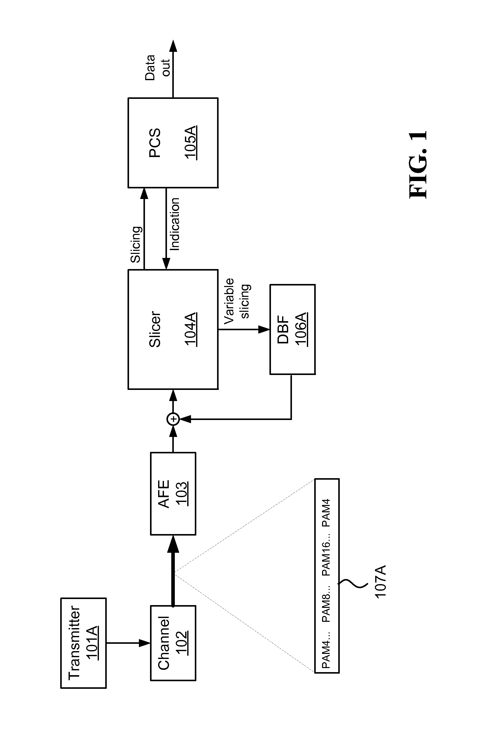
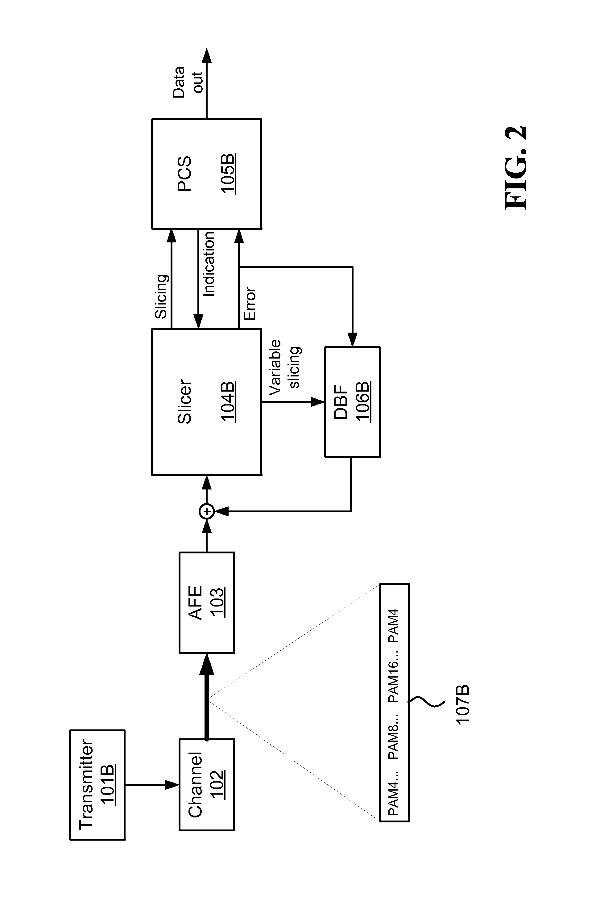
The patent text describes a system that uses signal modulation to increase data transfer rates, such as PAM4, and a Decision Based Filter (DBF) to reduce errors when decoding symbols. The system requires information about the type of modulation and values of the symbols entering the receiver. The performance of the DBF can be further improved by using slicing error associated with the slicing results. The technical effect of the patent text is to increase the accuracy and reliability of data transmission over a channel.

Problems solved by technology

When decoding symbols at the receiver, there is a chance for error due to interference.

Method used


Image

  • Methods for slicing dynamically modulated symbols
  • Methods for slicing dynamically modulated symbols
  • Methods for slicing dynamically modulated symbols

Examples


Embodiment Construction

[0017]In the following description, numerous specific details are set forth. However, the embodiments of the invention may be practiced without some of these specific details. In other instances, well-known hardware, software, materials, structures and techniques have not been shown in detail in order not to obscure the understanding of this description. In this description, references to “one embodiment” or “an embodiment” mean that the feature being referred to may be included in at least one embodiment of the invention. Moreover, separate references to “one embodiment” in this description do not necessarily refer to the same embodiment. Illustrated embodiments are not mutually exclusive, unless so stated and except as will be readily apparent to those of ordinary skill in the art. Thus, the invention may include any variety of combinations and / or integrations of the embodiments described herein. Also herein, flow diagrams illustrate non-limiting embodiment examples of the methods...


PUM


Abstract

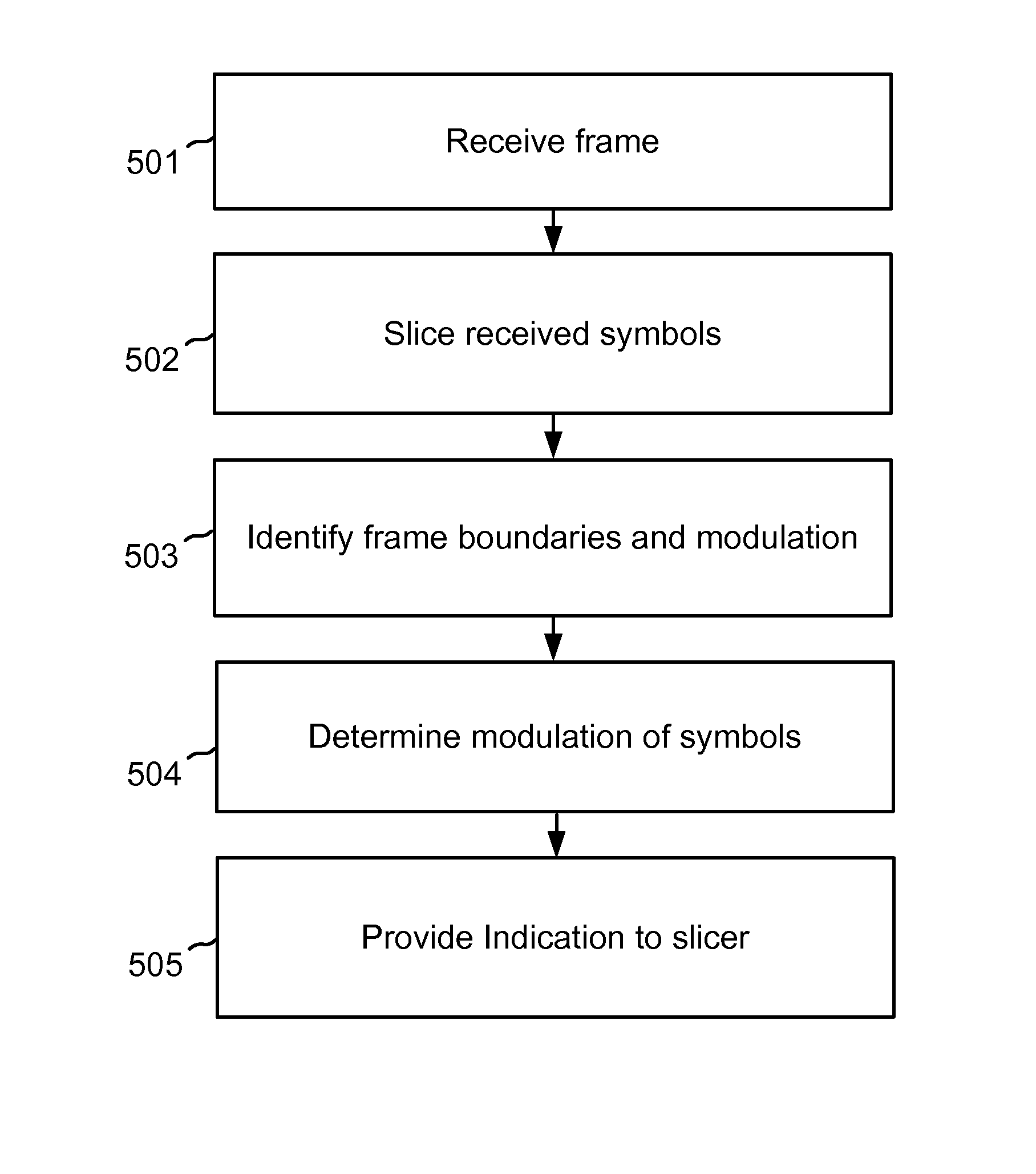
Reducing decision based filter error propagation by feedback from a physical coding sublayer (PCS) to a slicer. One method includes: receiving a frame comprising symbols of at least two different modulation orders that use subsets of a symbol superset; slicing the received symbols according to the highest modulation order by a slicer having slicing functions suitable for the different modulations; identifying frame boundaries and modulation information, which are modulated according to a predetermined modulation order; using the identified modulation information for determining the modulation of a nonempty set of dynamically modulated symbols in the received frame; and providing the slicer with an indication of which slicer function output to use for feeding a decision based filter.

Description

BACKGROUND[0001]In some embodiments, a transmitter transmits a packet comprising symbols over a channel to a receiver. The symbols are modulated according to the data they carry, such that symbols carrying different data types may be modulated with different modulations. The different modulations used for successive symbols within the same packet are selected from a subset of the same symbol set, or at least from partially overlapping subsets of the same symbol set. For example, a single packet may include X symbols modulated using PAM4, then Y symbols modulated using PAM8, then Z symbols modulated using PAM16, and then again X symbols modulated using PAM4. As a result, in order to decode the transmission properly, the receiver should determine the proper modulation for decoding each symbol or set of symbols. Referring to the last example, the receiver should demodulate the first X symbols using a PAM4 slicer, then demodulate the next Y symbols using a PAM8 slicer, then demodulate t...

Claims


Application Information

Patent Timeline
Patent Type & Authority Patents(United States)
IPC IPC(8): H03M13/00
CPCH03M13/09H04L1/0003H04L25/03057H04L25/03146H04L25/062H04L27/0008H04L27/0012H04L1/0036H04L2025/03363H04L1/00H04L5/0007H04L5/0044H04L25/03006
Inventor LIDA, EYRANCOHEN, GABY GURSALAMON, AVIV
Owner VALENS SEMICON
Learn More