Bending sensor
a technology of bending sensor and bending force, which is applied in the direction of material strength using steady bending force, force/torque/work measurement apparatus, instruments, etc., can solve problems such as reducing electrical resistance, and achieve the effect of limited sensitivity variation and high sensitivity
- Summary
- Abstract
- Description
- Claims
- Application Information
AI Technical Summary
Benefits of technology
Problems solved by technology
Method used
Image

Examples
first embodiment
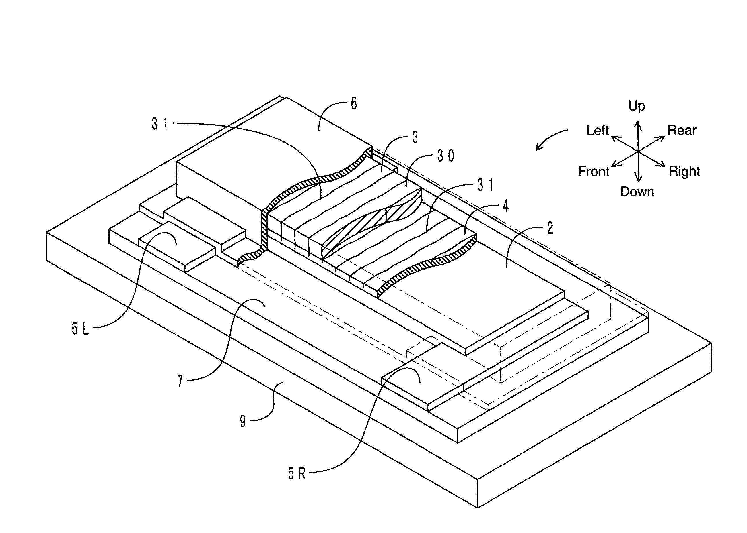
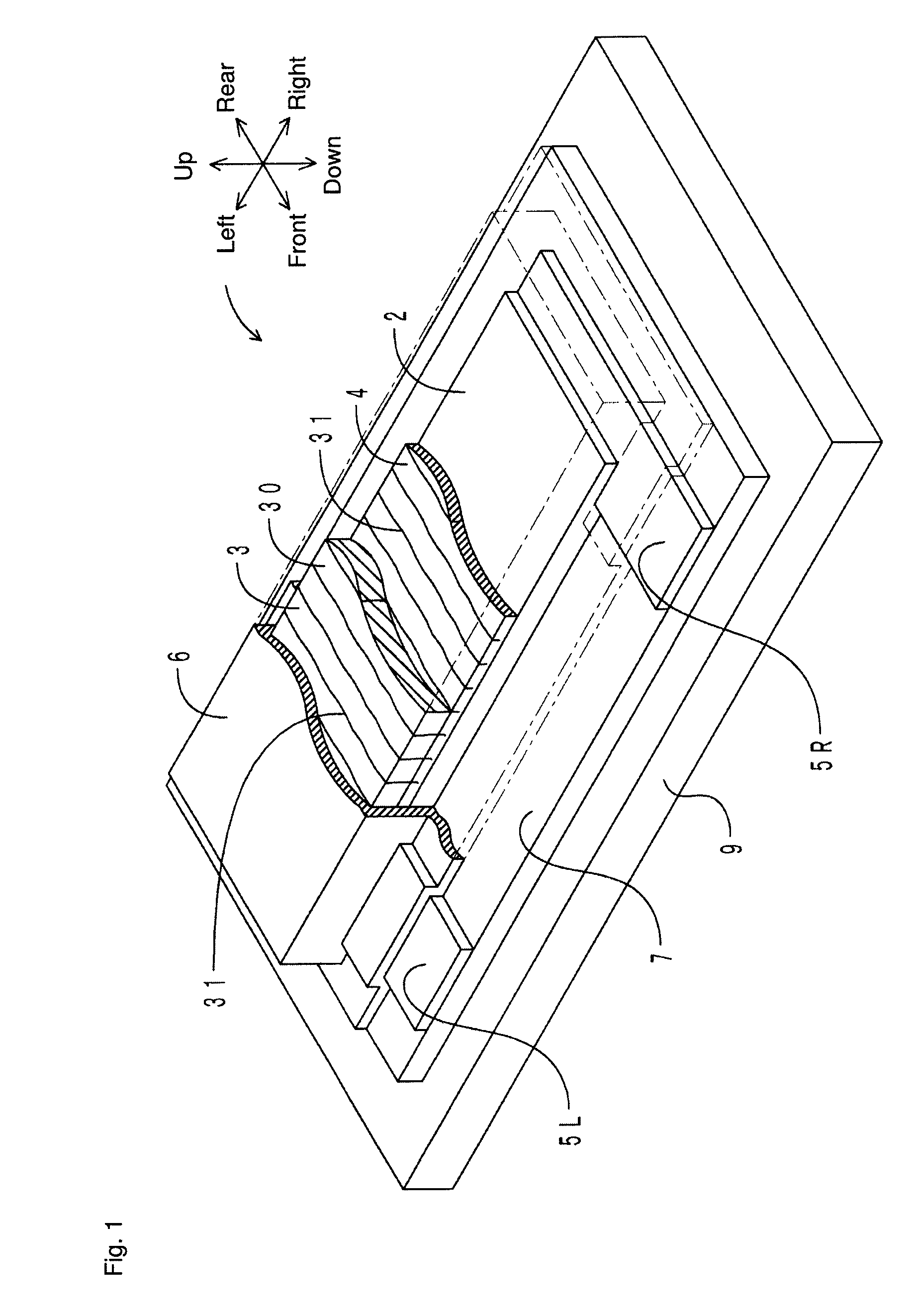
[0067]For ease of description, a length in a left-right direction is decreased and a length in an up-down direction (thickness) is increased relative to actual dimensions of a bending sensor in the drawings referred to below. In the drawings, the left-right direction corresponds to a “placement direction of a plurality of electrode portions” of the present invention. A front-rear direction corresponds to a “direction orthogonal to the placement direction of the plurality of electrode portions” of the present invention. The up-down direction corresponds to a “laminating direction” of the present invention. An upper side corresponds to a “load output side” of the present invention. A lower side corresponds to a “load input side” of the present invention.
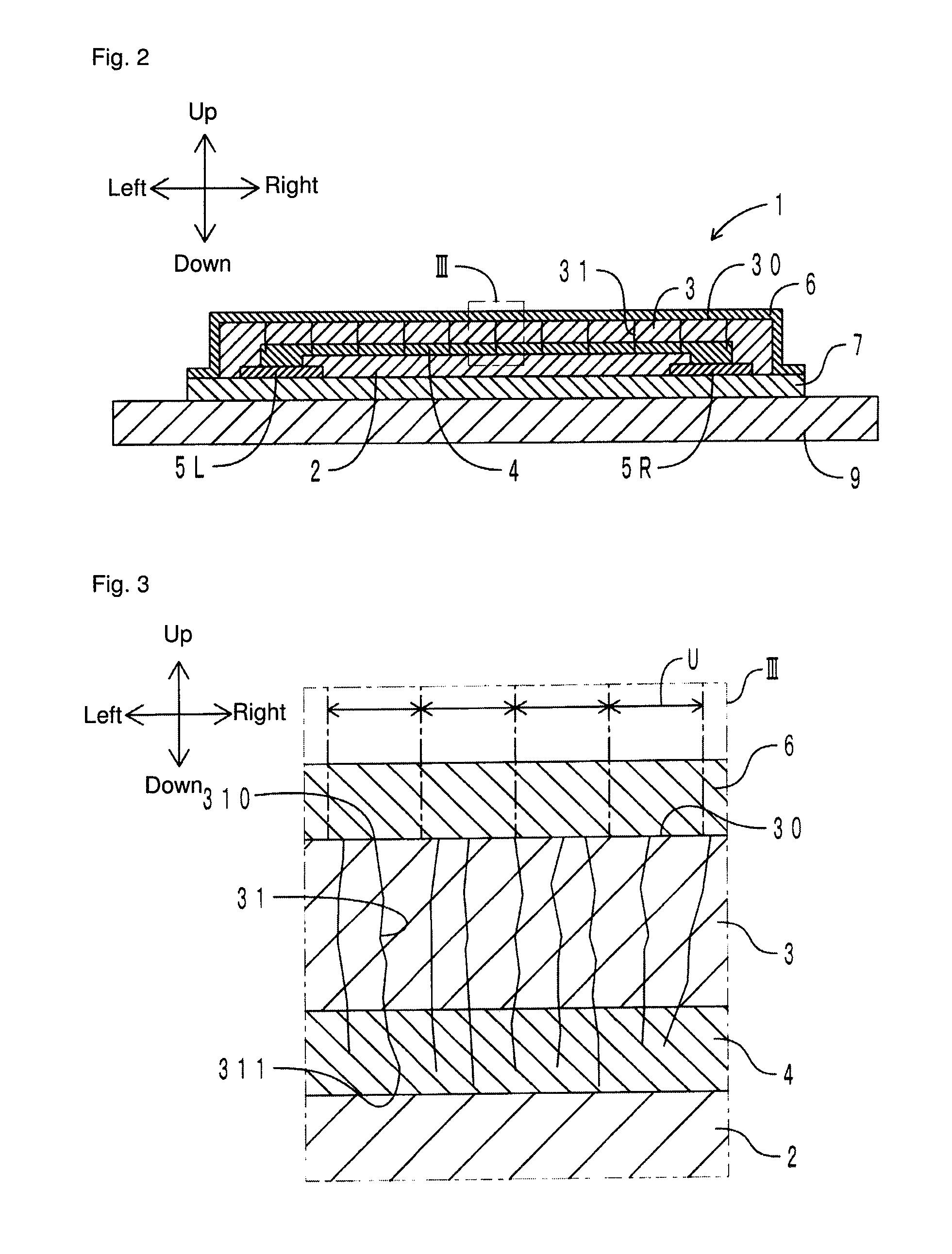
[0068]FIG. 1 is a transparent perspective view of the bending sensor according to the present embodiment. FIG. 2 is a cross-sectional view in the left-right direction of the bending sensor. FIG. 3 is an enlarged view of a portion in a ...
second embodiment
[0116]A bending sensor according to the present embodiment is different from the bending sensor of the first embodiment only in a shape of a high resistance layer. Only the difference is described herein. FIG. 9 is a transparent perspective view of the bending sensor according to the present embodiment. Components corresponding to those in FIG. 1 are denoted with the same reference numerals.
[0117]With reference to FIG. 9, a high resistance layer 2 of a bending sensor 1 is disposed in an S shape between a pair of electrode portions 5L and 5R. Specifically, the high resistance layer 2 has a front portion 2a, a central portion 2b, and a rear portion 2c, which are continuous and formed into an S shape. The front portion 2a, the central portion 2b, and the rear portion 2c each extend in the left-right direction. A left end of the front portion 2a is connected to the electrode portion 5L. A right end of the rear portion 2c is connected to the electrode portion 5R.
[0118]With reference to F...
third embodiment
[0120]A bending sensor according to the present embodiment is different from the bending sensor of the first embodiment in that a high resistance layer is disposed on a surface on a load input side of a base material. Only the difference is described herein. FIG. 10 is a cross-sectional view in the left-right direction of the bending sensor according to the present embodiment. Components corresponding to those in FIG. 2 are denoted with the same reference numerals.
[0121]With reference to FIG. 10, a high resistance layer 2 is printed on a lower surface of a base material 7. The base material 7 is included in a concept of a “reinforcement layer” of the present invention. A pair of electrode portions 50L and 50R is disposed at each of a left and right end (each longitudinal end) of the high resistance layer 2. The high resistance layer 2 and the pair of electrode portions 50L and 50R are covered by a covering layer 90 from below. On an upper surface of the base material 7, an insulatin...
PUM
| Property | Measurement | Unit |
|---|---|---|
| resistance | aaaaa | aaaaa |
| length | aaaaa | aaaaa |
| length | aaaaa | aaaaa |
Abstract
Description
Claims
Application Information
 - R&D
- Intellectual Property
- Life Sciences
- Materials
- Tech Scout
- Unparalleled Data Quality
- Higher Quality Content
- 60% Fewer Hallucinations
Browse by: Latest US Patents, China's latest patents, Technical Efficacy Thesaurus, Application Domain, Technology Topic, Popular Technical Reports.
© 2025 PatSnap. All rights reserved.Legal|Privacy policy|Modern Slavery Act Transparency Statement|Sitemap|About US| Contact US: help@patsnap.com