
Optical head-mounted display with mechanical one-dimensional scanner

a head-mounted display and scanner technology, applied in the field of image display devices, can solve the problems of users not being able to see the traffic around them, necks and hands, and users feeling uncomfortable, and achieve the effect of improving the optical head-mounted display and less photon energy loss

Active Publication Date: 2015-01-13
NAT CENT UNIV
View PDF2 Cites 7 Cited by
  • Summary
  • Abstract
  • Description
  • Claims
  • Application Information

AI Technical Summary

Benefits of technology

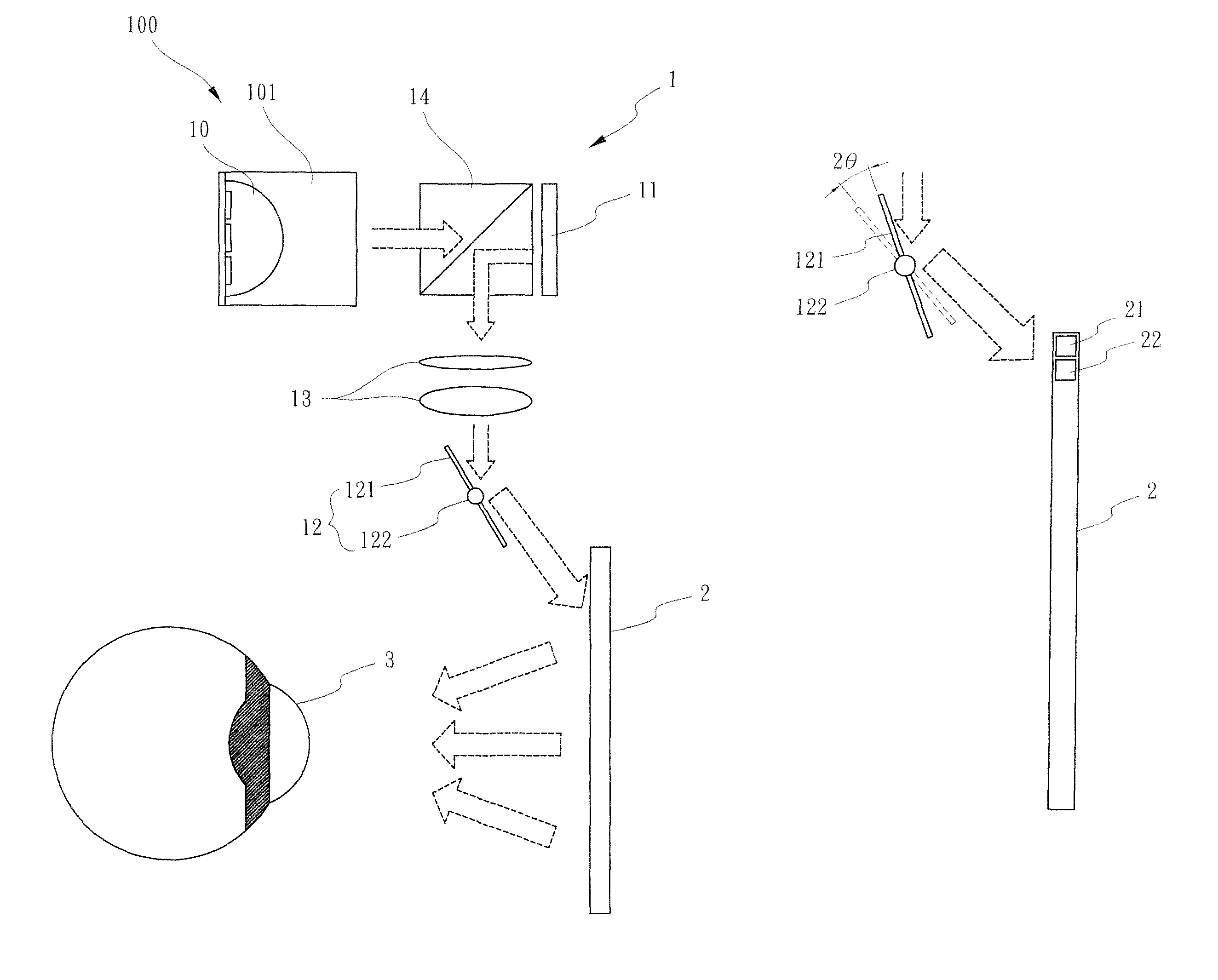
The present invention is an improved optical head-mounted display that reduces energy loss of photons. It includes an eyeglass frame, a holographic optical element, and a projector. The projector has a LED light source, a beam-splitting polarizer, a spatial light modulator, a lens set, and a mechanical one-dimensional scanner. The holographic optical element allows light to pass through and has properties of wavelength selectivity and angle selectivity. The technical effect of this invention is to provide a more efficient and effective optical head-mounted display.

Problems solved by technology

However, to watch the video or movie on these portable devices for several hours often causes people to feel uncomfortable, especially on their necks and hands.
Unfortunately, the image display device still has one shortcoming.
The users cannot be aware of the traffic around themselves when they wear the image display to go on the road because the image mapped from the image display device occupies the user's eyes and the view around the user cannot be transparent into the user's eyes.
Although some manufacturers try to use beam splitters or light guide devices to overcome this shortcoming, the image becomes ambiguous because of the energy loss of photons.

Method used


Image

  • Optical head-mounted display with mechanical one-dimensional scanner
  • Optical head-mounted display with mechanical one-dimensional scanner
  • Optical head-mounted display with mechanical one-dimensional scanner

Examples


Embodiment Construction

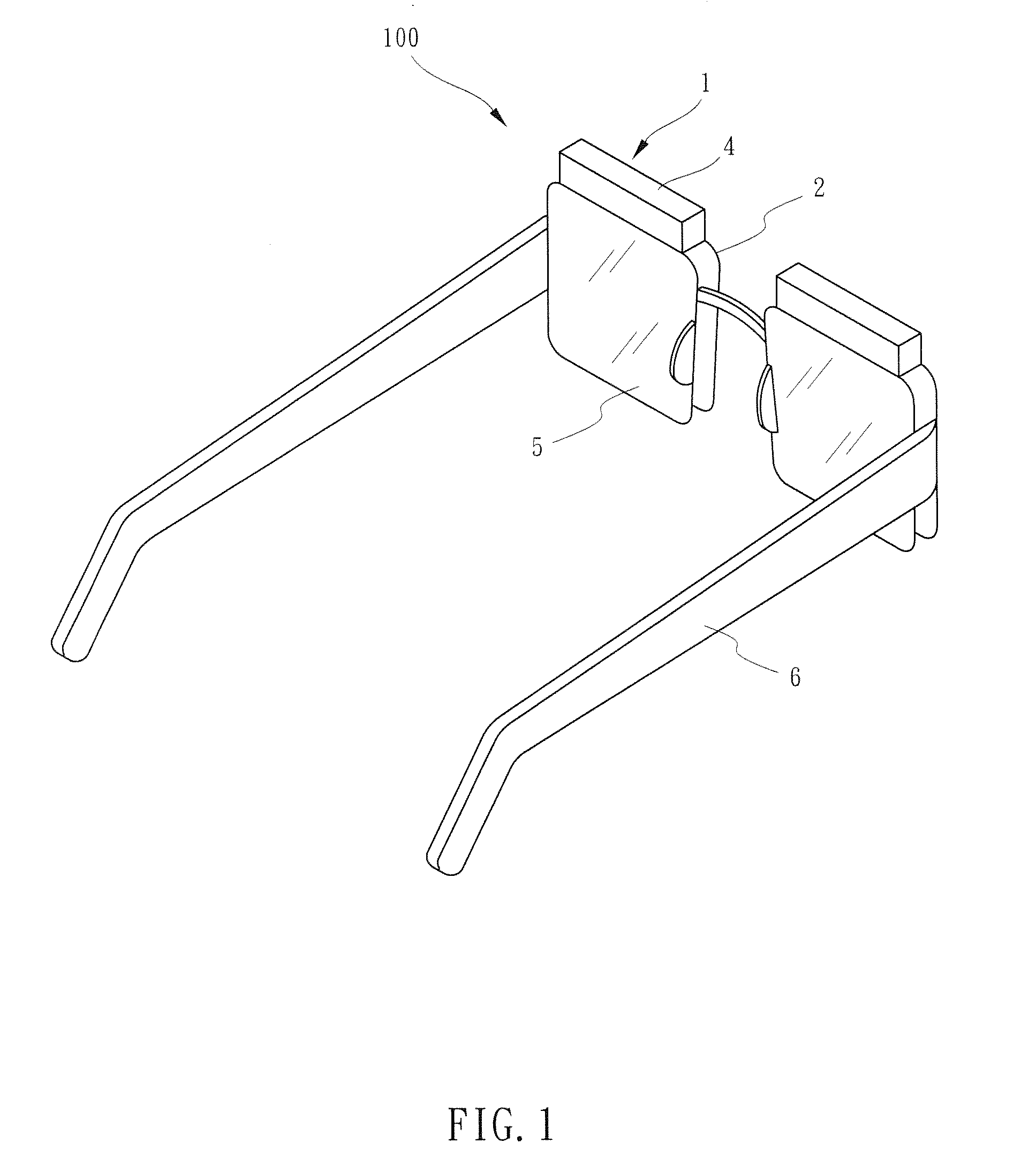
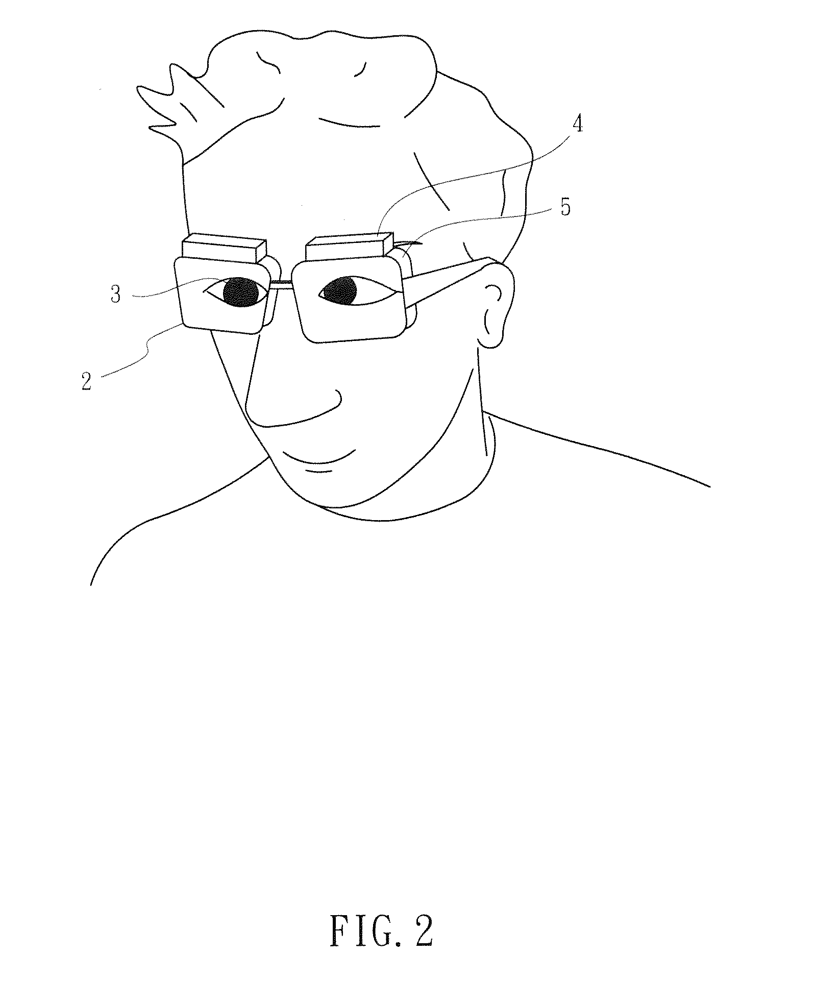
[0020]Referring to FIG. 1, there is shown an optical head-mounted display 100 constructed in accordance with a first embodiment of the present invention. The optical head-mounted display 100 generally comprises an eyeglass frame 6, a pair of eyeglass lens 5, at least one holographic optical element (HOE) 2 supported by the eyeglass frame 6 to be confronted by an eye of a wearer (see FIG. 2), and at least one projector 1 housed in a casing 4 and mounted on an upper edge of the eyeglass frame 6 to project image information on the holographic optical element 2. In particular, the holographic optical element 2 may be placed in front of the eyeglass lens 5 so that the light beams diffracted or reflected by the holographic optical element 2 will pass through the eyeglasses 5 to be mapped onto the user's pupils 3. Since the holographic optical element 2 also allows light to pass through, objects behind can be seen clearly. Thus, the optical head-mounted display 100 provides digital images ...


PUM


Abstract

An optical head-mounted display includes an eyeglass frame, a holographic optical element supported by the eyeglass frame to be confronted by an eye of a wearer, and a projector mounted on the eyeglass frame to project image information on the holographic optical element. The projector includes a LED light source, a beam-splitting polarizer, a spatial light modulator, a lens set and a mechanical one-dimensional scanner. The mechanical one-dimensional scanner reflects the transformed light beam from the lens set onto the holographic optical element in one dimension at a time. When the reflective sheet is rotated at a range of angle in a brief moment of time, the holographic optical element receives from the rotating reflective sheet an array of one-dimensional modulated light beams and reflects the latter to form a two-dimensional image in the eye because of persistence of vision.

Description

CROSS-REFERENCE TO RELATED APPLICATION[0001]This is a continuation-in-part of co-pending application Ser. No. 13 / 280,560, filed Oct. 25, 2011, currently pending.BACKGROUND OF THE INVENTION[0002]1. Field of the Invention[0003]The present invention relates to an image display device, more particularly to an optical head-mounted display for projecting image onto pupils of human eyes.[0004]2. Description of Related Art[0005]Nowadays, LCD panels are widely used to the portable devices, such as smart phones, tablet computers, handheld video game devices . . . etc. Thus, people can enjoy different kinds of entertainments from these portable devices in the leisure time. However, to watch the video or movie on these portable devices for several hours often causes people to feel uncomfortable, especially on their necks and hands.[0006]In order to improve the shortcoming mentioned above, a manufacturer designs one image display device which is worn on a user's head. The image display device us...

Claims


Application Information

Patent Timeline
Patent Type & Authority Patents(United States)
IPC IPC(8): G03H1/00G02B5/32G02B26/10G02B27/01
CPCG02B27/0172G02B5/32G02B26/10
Inventor SUN, CHING-CHERNG
Owner NAT CENT UNIV
Learn More