
Buckstay connecting system

a technology of connecting system and buckstay, which is applied in the direction of mechanical equipment, machines/engines, light and heating equipment, etc., can solve the problems of buckstay displacement, weak stiffness, and failure to perfectly inhibit such deformation, so as to reduce construction materials, and reduce the burden on welding work

Active Publication Date: 2015-01-27
IHI CORP
View PDF13 Cites 0 Cited by
  • Summary
  • Abstract
  • Description
  • Claims
  • Application Information

AI Technical Summary

Benefits of technology

The present invention is a buckstay connecting system designed to reduce the burden on welding work and the amount of construction materials used. The system includes an insertion part that can be fastened to a socket part for securely coupling vertical and horizontal buckstays. When the horizontal buckstay is installed and supported, the insertion part can slide in the vertical direction to further prevent the horizontal buckstay from falling. Additionally, the insertion part is separated from the vertical buckstay, reducing the length of the vertical buckstay and permitting easier installation. Overall, the invention reduces the workload and materials required for construction.

Problems solved by technology

The furnace wall is supported in such a way that it is suspended from a building covering to build a furnace, and thus has weak stiffness.
However, the buckstays prevent excessive deformation of the furnace, but fail to perfectly inhibit such deformation.
As such, when the furnace is deformed by thermal expansion, this leads to displacement of the buckstays.
Since these temporary construction materials need to support all the horizontal buckstays ready to fall in a horizontal state, too many construction materials are required.
As such, the temporary construction materials for supporting the horizontal buckstays are attributed to increasing the period and cost of construction when constructing, for example, the thermal electric power plant.
For this reason, the welding work is great in the construction field, which leads to increasing the period and cost of construction.

Method used


Image

  • Buckstay connecting system
  • Buckstay connecting system
  • Buckstay connecting system

Examples


Embodiment Construction

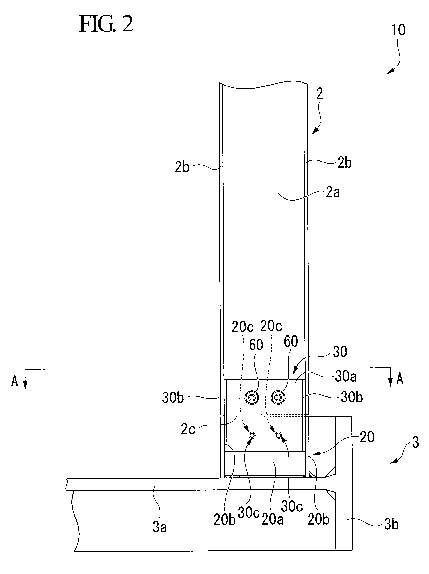
[0030]Hereinafter, an embodiment of a buckstay connecting system related to the present invention will be described with reference to the accompanying drawings. Further, in the drawings, the scale of each member is appropriately modified so as to make the size of each member recognizable.

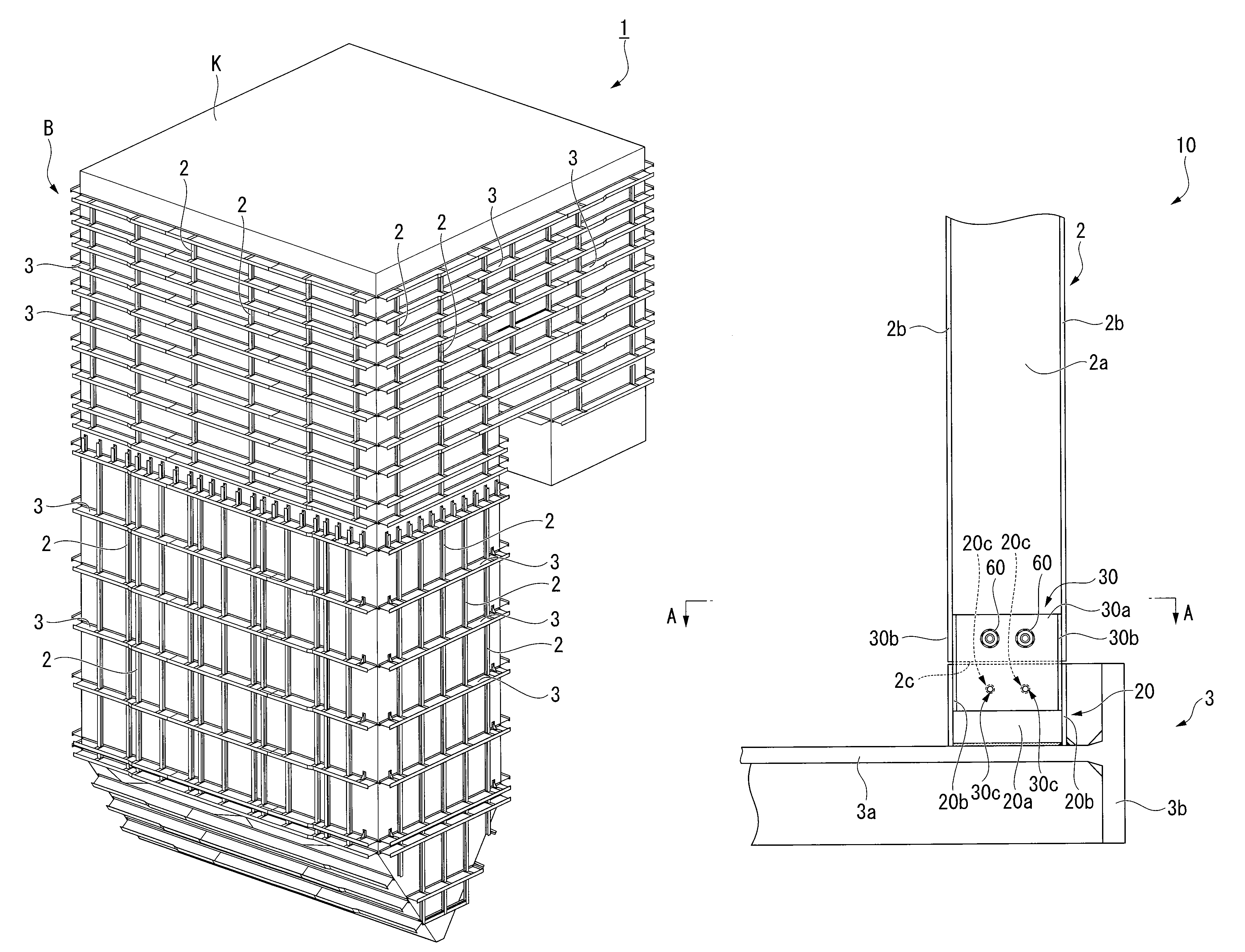
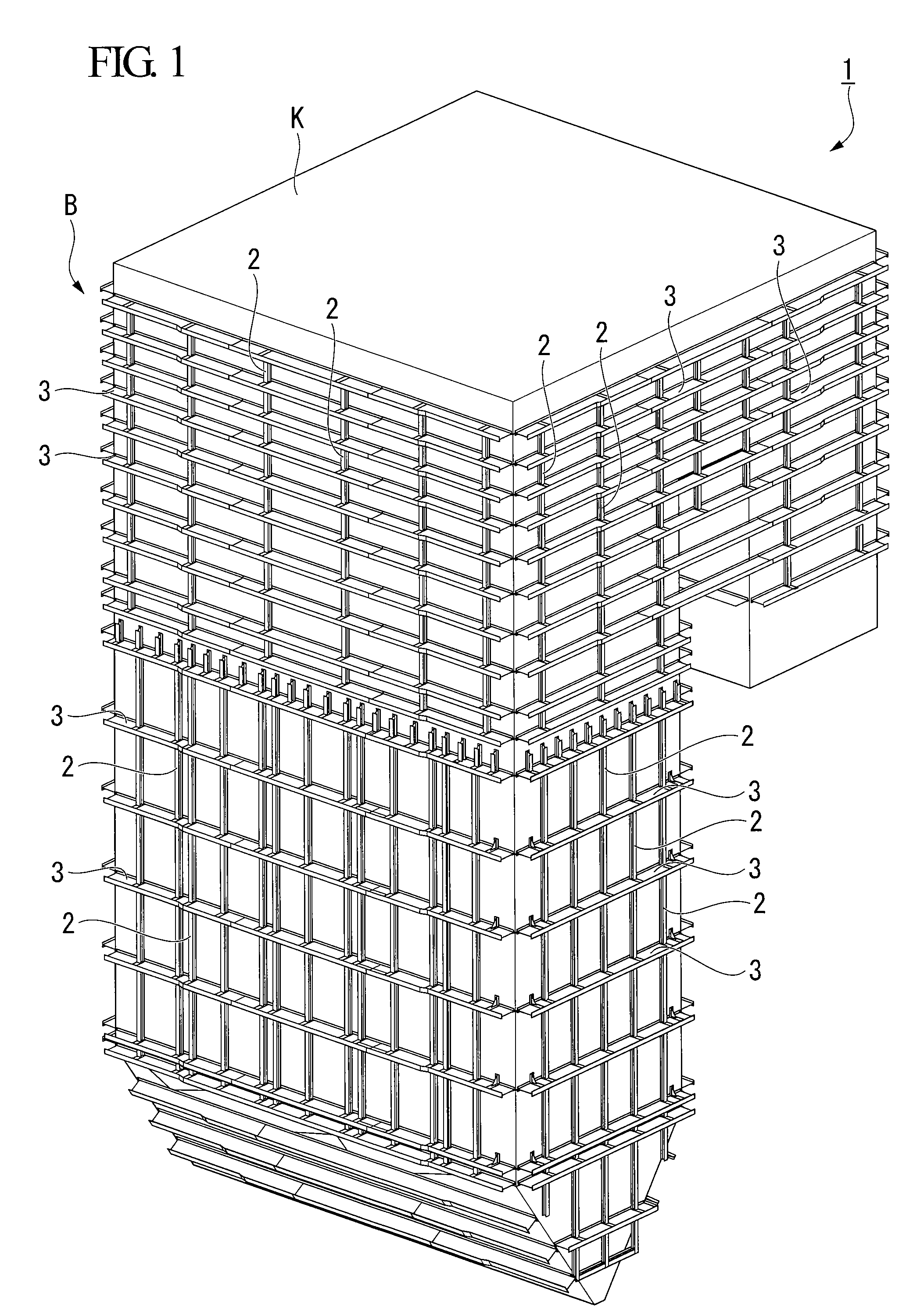
[0031]FIG. 1 is a perspective view of a buckstay 1 installed around a furnace B. The buckstay 1 is disposed a predetermined distance apart from a furnace wall of the furnace B, and is connected with the furnace B by supports (not shown), thereby inhibiting deformation of the furnace B. The buckstay 1 itself is supported by suspension from, for example, a support structure K installed on the furnace B along with the furnace B.

[0032]As shown in FIG. 1, the buckstay 1 is made up of vertical buckstays 2 installed in a height direction of the furnace B, and horizontal buckstays 3 installed in a width direction of the furnace B.

[0033]The horizontal buckstays 3 are disposed so as to surround the entire cir...


PUM


Abstract

A buckstay connecting system includes a socket part that is fixed to the horizontal buckstay being separated from a lower end of the vertical buckstay between the lower end of the vertical buckstay and the horizontal buckstay, and an insertion part that is fixed to a lower portion of the vertical buckstay, is inserted into the socket part so as to be able to slide in a vertical direction, inhibits the horizontal buckstay from being inclined, and is allowed to be fastened to the socket part.

Description

BACKGROUND OF THE INVENTION[0001]1. Field of the Invention[0002]The present invention relates to a buckstay connecting system, and more particularly, to a buckstay connecting system for connecting a vertical buckstay installed in a height direction of a furnace with a horizontal buckstay installed in a width direction of the furnace.[0003]This application claims priority to and the benefits of Japanese Patent Application No. 2009-243278 filed on Oct. 22, 2009, the disclosure of which is incorporated herein by reference.[0004]2. Background Art[0005]As is widely known, furnaces installed on, for example, thermal electric power plants have a furnace wall made up of a plurality of water pipes and fins interposed between the water pipes.[0006]The furnace wall is supported in such a way that it is suspended from a building covering to build a furnace, and thus has weak stiffness. For this reason, in order to enhance the stiffness of the furnace wall and to inhibit the furnace from being g...

Claims


Application Information

Patent Timeline
Patent Type & Authority Patents(United States)
IPC IPC(8): F22B37/24F22B21/00F22B37/20
CPCF22B37/208F22B37/244F22B21/00
Inventor KIKUCHI, KATSUMI
Owner IHI CORP
Learn More