
Weaving machine having movable shed opening limiter device

Inactive Publication Date: 2015-01-27
LINDAUER DORNIER GMBH
View PDF14 Cites 9 Cited by
  • Summary
  • Abstract
  • Description
  • Claims
  • Application Information

AI Technical Summary

Benefits of technology

The present invention aims to provide a weaving machine that can reduce the risk of damaging the weft material, especially band-shaped or tape-shaped weft materials. It also aims to overcome the shortcomings of the prior art and provide additional advantages. The goal of the invention is to achieve these objects without requiring a limitation on the claimed invention.

Problems solved by technology

For producing woven fabrics of band-shaped or tape-shaped materials, the known solutions are, however, largely not suitable.
Thus, with band-shaped materials or materials containing reinforcement fibers, which comprise a lower flexibility than typical conventional thread-shaped materials, it can lead to deformations caused by handling devices of the weaving machine, and as a result to damages of the band or tape material.
With band-shaped weft materials, due to their width, it can lead to a wave formation in the weft direction, which makes it more difficult to form flat woven fabrics.
Also, with use of band-shaped materials as weft material, a typical conventional weft beat-up by means of a weaving reed is not possible, because this would give rise to damages and deformations on the band-shaped weft material.
On the other hand, without a weft beat-up, it is not possible to produce a uniform dense or tight woven fabric.
Because the clamping of the original fabric edge is released during the rotation of the rollers for the clamping of the last inserted weft material, in this case also, it can still give rise to gaps in the woven fabric or an insufficient weft density or weft set.
Furthermore, it can lead to damages of the weft material caused by the rollers.

Method used


Image

  • Weaving machine having movable shed opening limiter device
  • Weaving machine having movable shed opening limiter device
  • Weaving machine having movable shed opening limiter device

Examples


Embodiment Construction

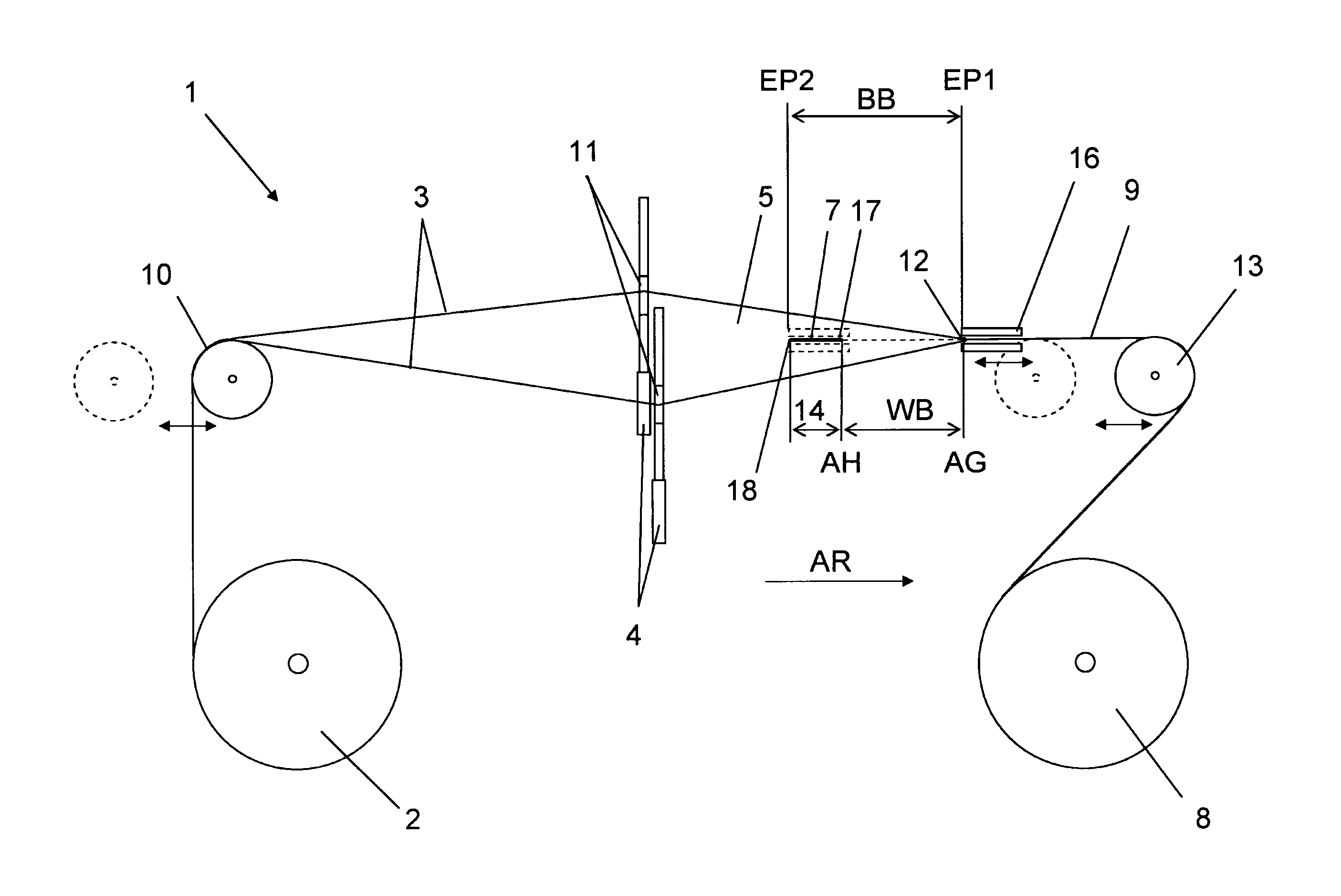
[0030]FIG. 1 shows a weaving machine 1 according to the invention in a schematic side view. The weaving machine 1 in a known manner includes a warp beam or roll 2 from which a warp material 3 is provided, shedding means 4 for forming a loom shed 5, as well as weft insertion means 6 (presently not shown, see FIG. 6) for the insertion of a preferably band-shaped weft material 7 into the loom shed 5. The warp material can alternatively be provided from a creel with a plurality of warp spools or bobbins from which the warp material is drawn off. Furthermore, drawing-off or take-off means 8 for drawing off the finished goods or woven fabric 9 in a drawing-off or take-off direction AR (presently symbolized by an arrow) are provided. In a conventional manner the warp material 3 can be embodied thread-shaped, or also band-shaped. In a manner known as such, the warp material 3 is guided from the warp beam 2 over a backrest beam or whip roll 10 through the heddle eyelets 11 of the shedding me...


PUM


Abstract

A weaving machine for producing a woven fabric has a shedding device to form a loom shed of warp material, a weft insertion device for inserting a preferably tape-shaped or band-shaped weft material into the loom shed, a drawing-off device for drawing off the finished fabric in a drawing-off direction, fabric movement device for moving the fabric back and forth in the warp direction to bring the last inserted weft material into contact with the binding point or fabric edge. A shed limiter device limits the opening of the loom shed from above and below the warp, and is movable back and forth in the warp direction. The shed limiter device only loosely bounds the fabric and essentially without actively clamping or pinching or contacting the fabric and / or the last inserted weft material, at least while moving in the direction opposite the drawing-off direction.

Description

FIELD OF THE INVENTION[0001]The present invention relates to a weaving machine or loom for producing a woven fabric with shedding means for alternately raising and lowering warp material for forming a loom shed, with weft insertion means that are arranged stationarily in the warp direction in a weft insertion position for inserting a preferably band-shaped or tape-shaped weft material into the loom shed, as well as with drawing-off means or take-off means for drawing off the finished woven fabric or material in a drawing-off or take-off direction. Furthermore, means for the fabric or material movement in the warp direction are provided, by means of which the fabric edge is movable in a fabric or material movement range, back and forth between a downstream initial position and an upstream collecting or pick-up position, in order to bring the respective last-inserted weft material into contact with the fabric edge in the collecting or pick-up position.BACKGROUND INFORMATION[0002]In th...

Claims


Application Information

Patent Timeline
IPC IPC(8): D03D51/00D03D49/00D03C13/00D03D41/00D03J1/22
CPCD03D41/00D03C13/00D03D41/008D03J1/22
Inventor JANICIJEVIC, DIRKLOUVEN, JOHANNESORTMANN, HUBERTMOTZ, KURTLAUKAMP, THOMASLANGER, MICHAELMUELLER, HERBERT
Owner LINDAUER DORNIER GMBH
Learn More