Methods and apparatus for establishing electrical connections to a railroad rail

a technology for electrical connections and rails, applied in rail devices, roads, constructions, etc., can solve the problems of reducing the current flow through the relay coil, and affecting the safety of the rail itself, so as to achieve the effect of facilitating replacement and reducing the damage to the rails

Active Publication Date: 2015-01-27
BNSF RAILWAY
View PDF2 Cites 15 Cited by
  • Summary
  • Abstract
  • Description
  • Claims
  • Application Information

AI Technical Summary

Benefits of technology

[0006]Embodiments of the present principles provide significant advantages over the prior art practice of welding or brazing electrical connections directly to the web of railroad rails. Specifically, because most of the work of making electrical connections is now performed on a wire bonding assembly, damage to the rails themselves is substantially reduced, particularly when cables and wires must be disconnected and reconnected at a given site. Among other

Problems solved by technology

On the other hand, when a locomotive and/or railcar is within the track block, the metal wheels and axels create an electrical shunt between the rails, which reduces the current flow though the relay coil and breaks the relay signal path.
While track circuits have been kno

Method used


Image

  • Methods and apparatus for establishing electrical connections to a railroad rail
  • Methods and apparatus for establishing electrical connections to a railroad rail
  • Methods and apparatus for establishing electrical connections to a railroad rail

Examples


Embodiment Construction

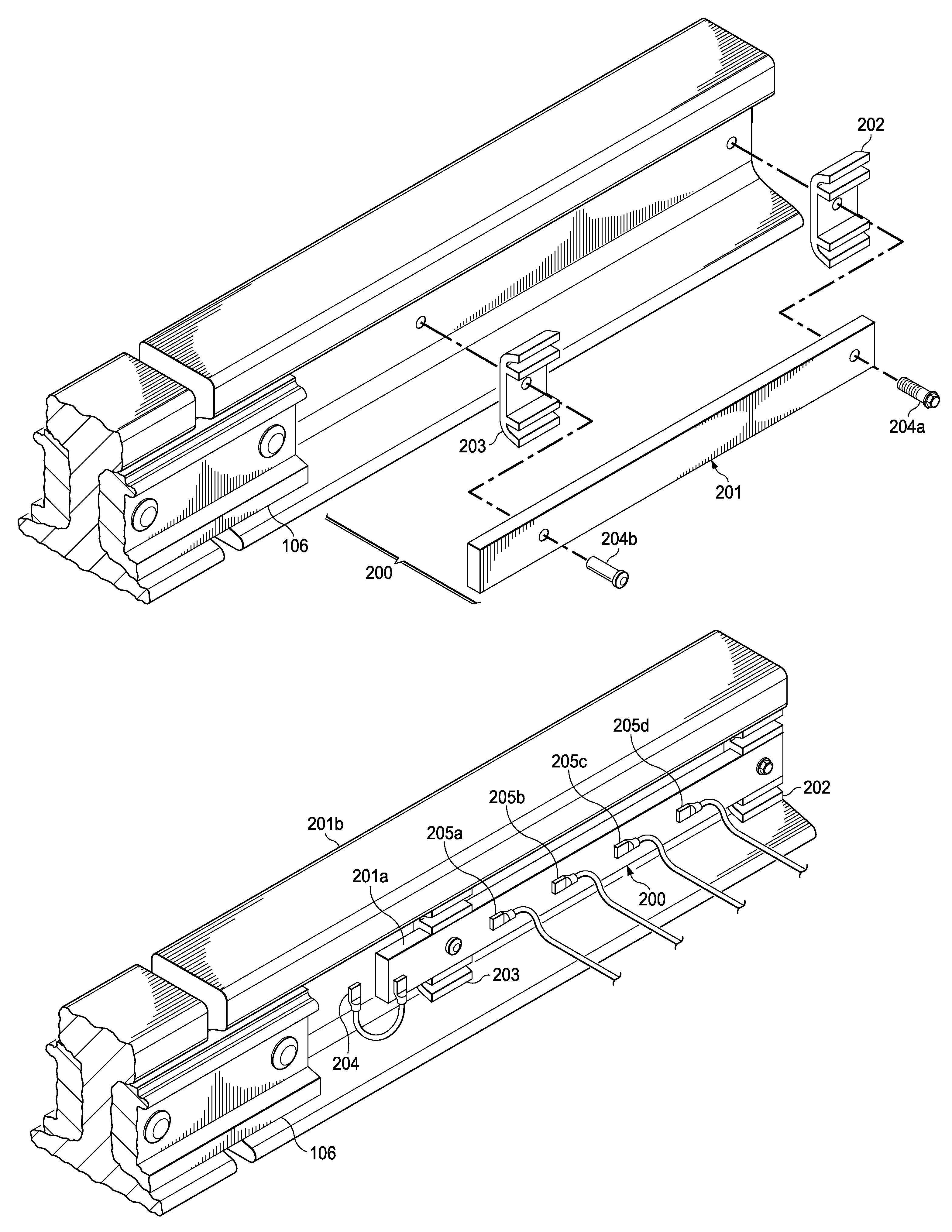
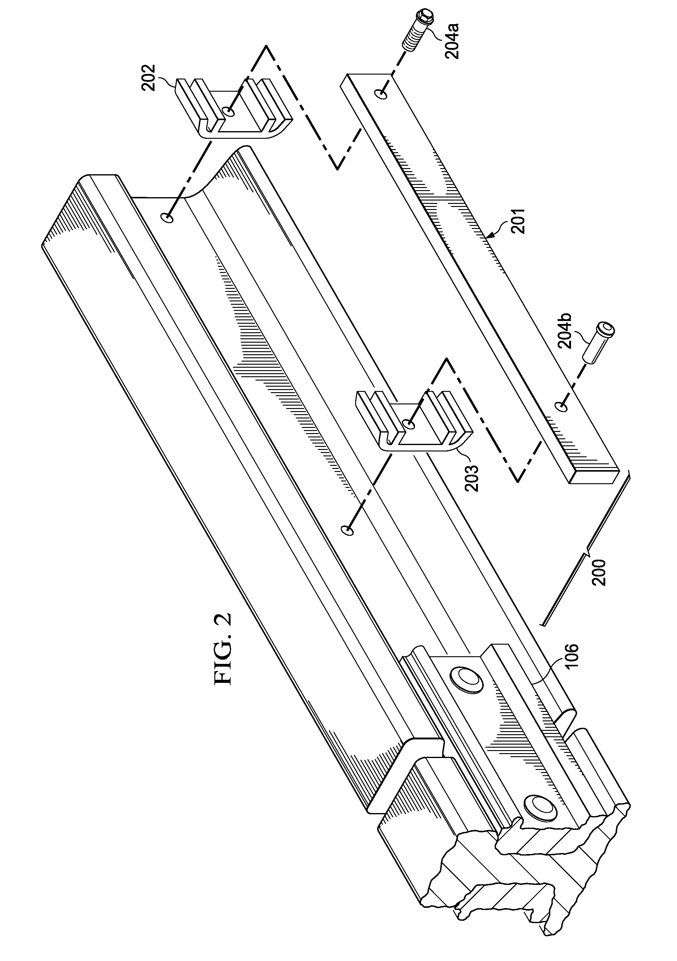
[0011]The principles of the present invention and their advantages are best understood by referring to the illustrated embodiment depicted in FIGS. 1-3 of the drawings, in which like numbers designate like parts.

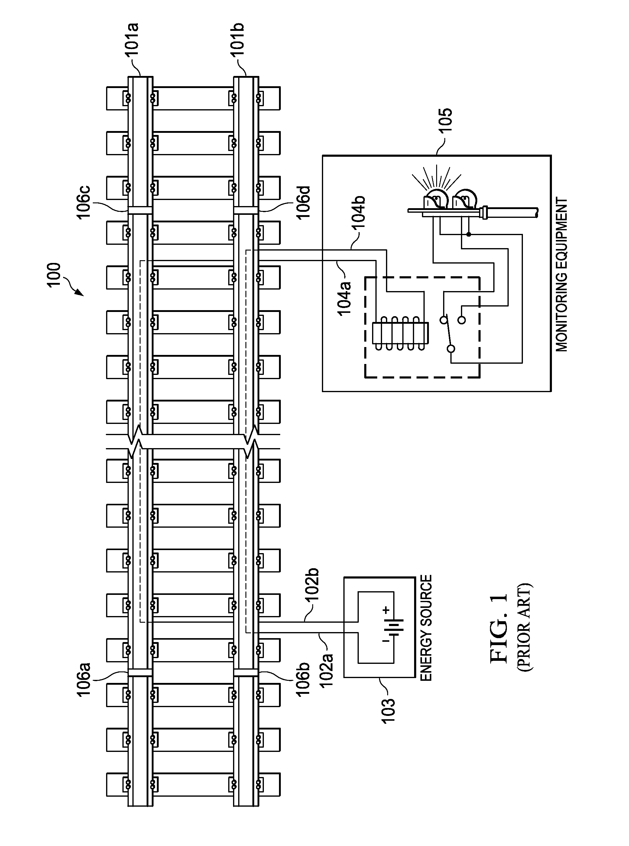
[0012]FIG. 1 is a diagram of small portion of a block 100 of railroad track including a pair of conventional parallel steel railroad rails 101a and 101b. Block 100 is associated with conventional track circuit equipment including an electrical energy source 103 connected to rails 101a and 101b through a corresponding pair of track wires 102a and 102b. Track wires 102a and 102b are connected to terminals of opposite polarity on electrical energy source 103 to create current flow through rails 101a and 101b when a closed circuit is maintained. While electrical energy source 103 is shown as a conventional direct current (DC) electrical source suitable for track circuit applications, electrical energy source 103 can also be a conventional alternating (AC) electrical source, as k...


PUM


Abstract

A method of making an electrical connection to a railroad rail includes fastening a wire bonding assembly to a railroad rail, the wire bonding assembly including first and second spaced apart washer plates contacting the rail and a metal bar supported by the washer plates. The metal bar is electrically connected with the rail with a first conductive lead contacting a selected point on the rail and a selected point on the metal bar. A second conductive lead is connected to another selected point on the metal bar for establishing an electrical connection to the rail from an electrical device.

Description

FIELD OF INVENTION[0001]The present invention relates in general to railroad equipment, and in particular, to methods and apparatus for establishing electrical connections to a railroad rail.BACKGROUND OF INVENTION[0002]Track circuits have been used by the railroads for many years. Generally, each of a pair of rails of a block of track is connected to terminals of opposite polarity of an electrical power source. These connections are normally made on the respective rails near the insulated joints separating one end of the track block with the end of the neighboring track block. The rails are also respectively connected, near the insulated joints at the other end of the block, to opposing terminals of the coil of a relay. Signal flow through the relay, under the control of the relay coil, is monitored by associated monitoring equipment, which in turn sets signal aspects, transmits messages to dispatchers, and so on.[0003]In a typical track circuit, when the block of track is clear (i...

Claims


Application Information

Patent Timeline
IPC IPC(8): B60M5/00
CPCB60M5/00
Inventor BOUSQUET, MARK E.HARMON, KURT D.
Owner BNSF RAILWAY
Why Eureka
Try Eureka