
Suspension system

a suspension system and suspension technology, applied in the direction of friction roller based transmission, steering device, cycle equipment, etc., can solve the problems of poor ride quality and potential wheel control problems, and the weight of the spring adds to the unsprung weight or weight,

Inactive Publication Date: 2015-01-27
AMERICAN DESIGN & MASTER CRAFT INITIATIVE
View PDF23 Cites 31 Cited by
  • Summary
  • Abstract
  • Description
  • Claims
  • Application Information

AI Technical Summary

Problems solved by technology

In addition, the weight of the spring adds to the unsprung weight or weight not supported by the suspension of the bike.
Generally, a greater amount of unsprung weight produces a poor ride quality and potential wheel control issues when accelerating or braking.

Method used


Image

  • Suspension system
  • Suspension system
  • Suspension system

Examples


Embodiment Construction

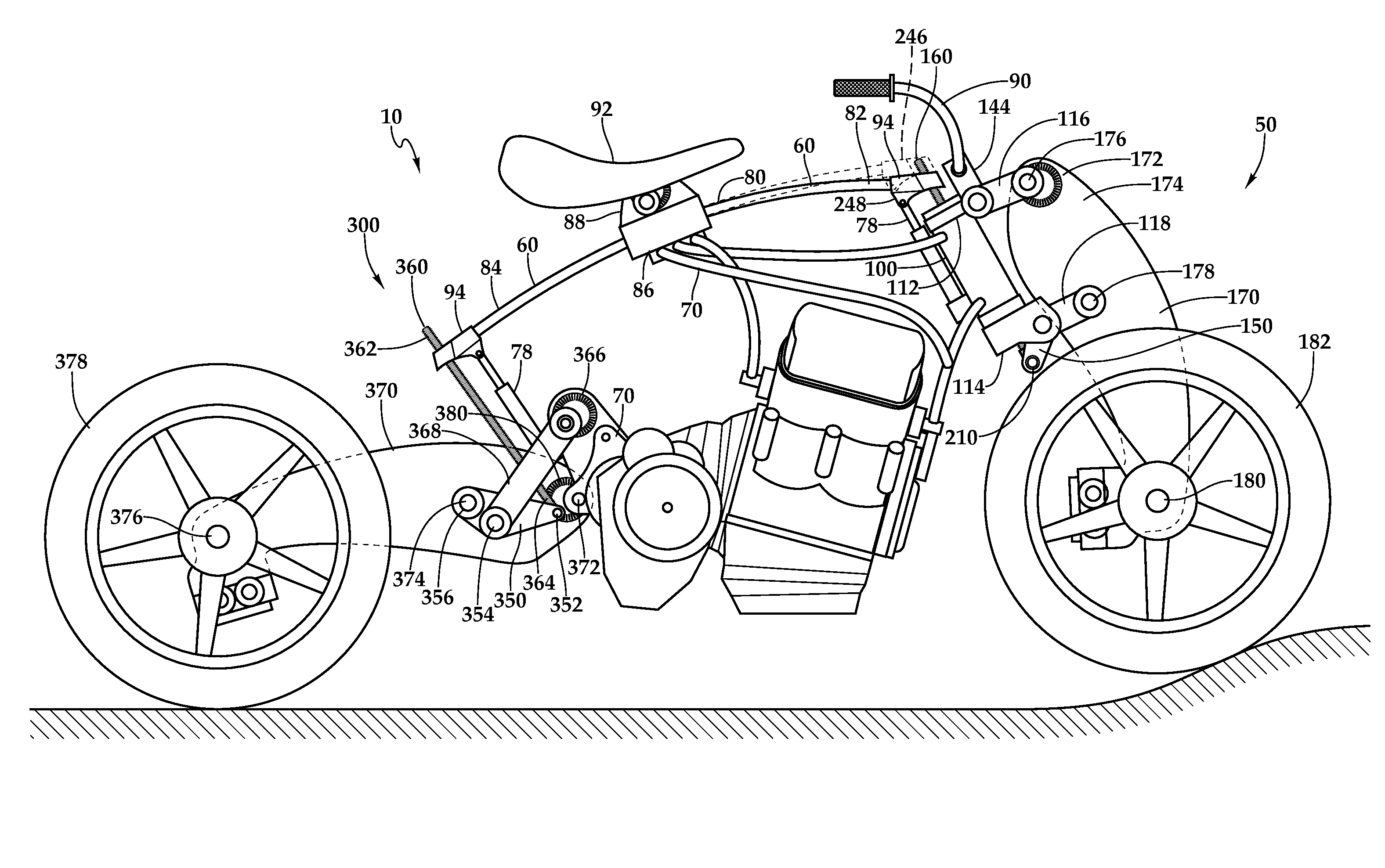
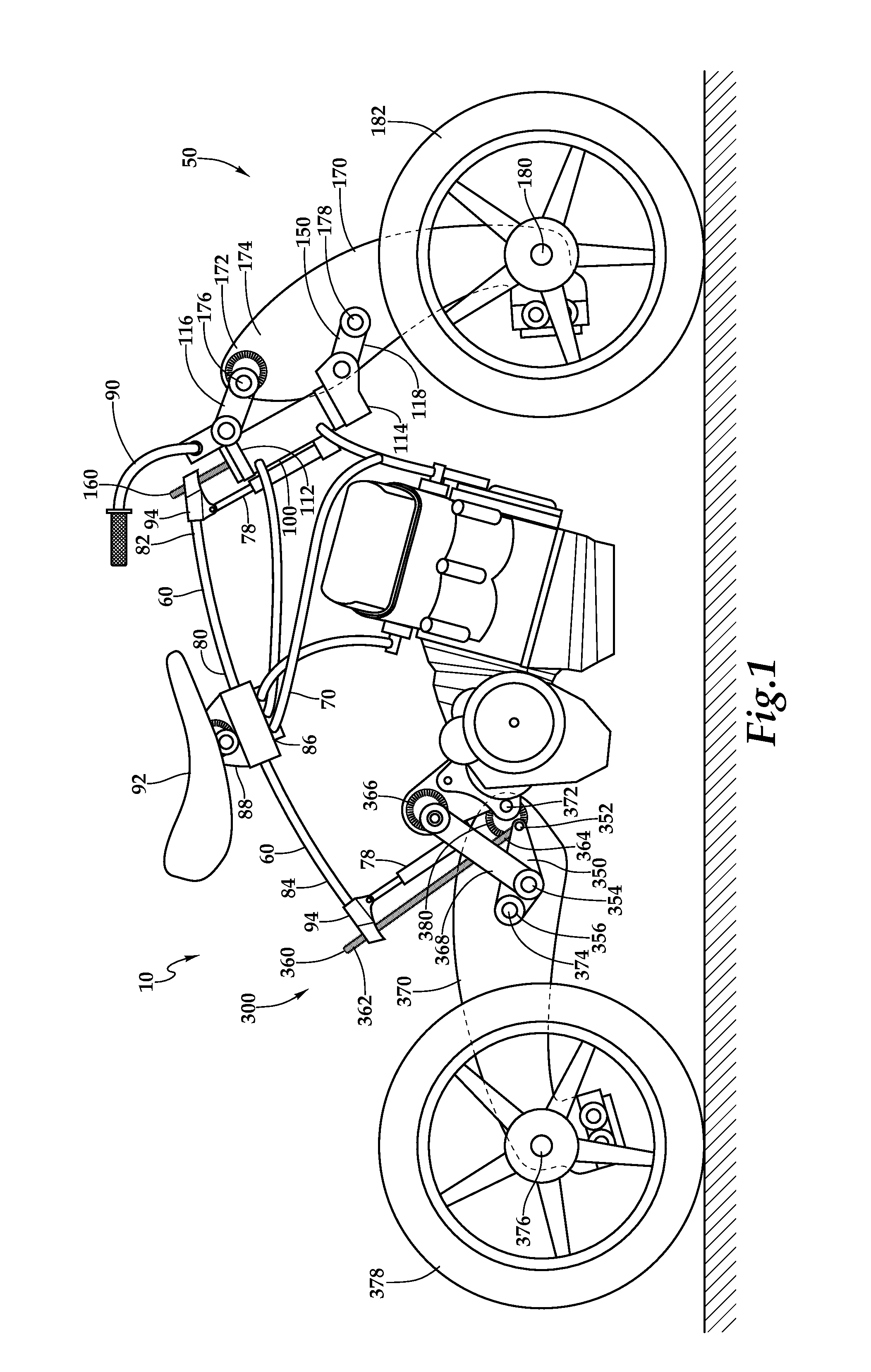
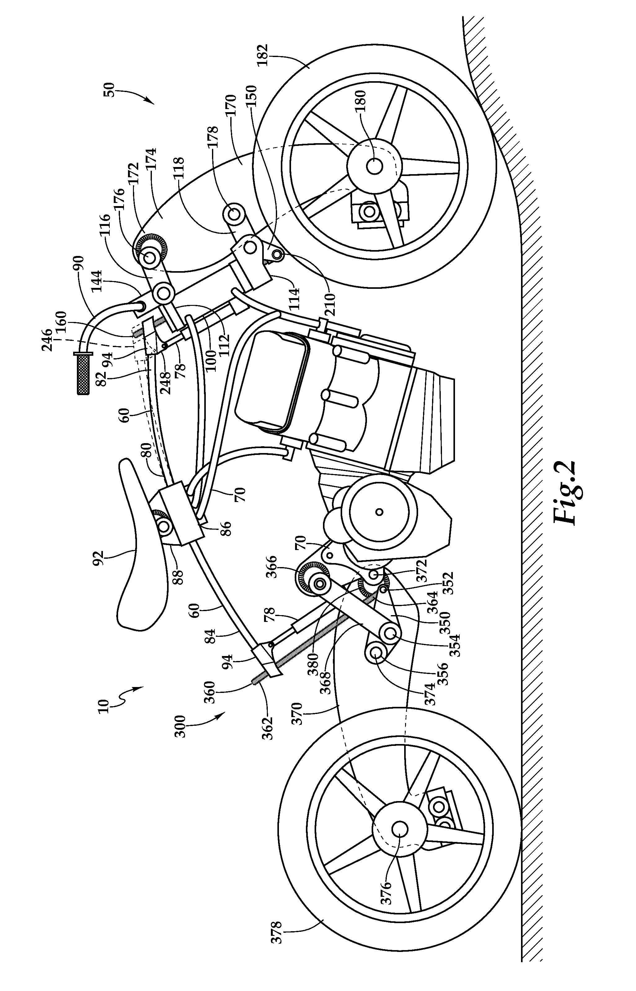
[0028]Referring now to FIGS. 1-2, an embodiment of a motorcycle suspension system 10 may comprise a front suspension 50 and a rear suspension 300. Front suspension 50 includes spring 60, neck assembly 100, front linkage 150, front suspension rod 160, and two front girder blades 170. Rear suspension 300 includes spring 60, rear linkage 350, rear suspension rod 360, and two rear girder blades 370. While shown as a suspension system for a motorcycle, it is also contemplated that front suspension 50 and rear suspension 300 be used in a bicycle. One of the front girder blades 170 and one of the rear girder blades 370 are removed to enable viewing of all components of front and rear suspensions.

[0029]In general, front suspension 50 has spring 60 mounted to chassis 70 and connected to front linkage 150 of neck assembly 100 by front suspension rod 160 extending through a hollow steering stem 106 of neck assembly 100 and having a first end 162 coupled to spring 60 and second end 164 coupled ...


PUM


Abstract

A vehicle suspension system includes a spring, a neck assembly, and a rod. The neck assembly has an outer shell housing a hollow stem having an upper end and a lower end. The stem is rotatable respect to outer shell. The upper end is coupled to an upper bracket having a control arm pivotally coupled thereto. The lower end is coupled to a lower bracket having a linkage pivotally connected thereto. The rod has a first end coupled to the spring and a second end coupled to the linkage. The rod extends through the hollow stem. The linkage is further coupled to a wheel assembly.

Description

BACKGROUND OF THE INVENTION[0001]The invention relates generally to vehicle suspension systems, and more particularly to a multi-link suspension system.[0002]Vehicle suspensions, specifically motorcycle and bicycle suspensions, are used to absorb bumps, cracks, and roadway deformities to provide a rider with a smoother ride and allow the rider to maintain control of the vehicle. A girder fork or girder front end is a common front end suspension in motorcycles. A traditional girder fork has a pair of uprights that is connected to a front wheel axle on one end and two links on the other end. A spring, most commonly a coil spring, connects the lower link to an upper link having a set of handle bars mounted thereon. Leaf springs have also been used as the spring in front suspensions. The leaf spring is mounted to a bracket extending above the front wheel and connects the girder forks or leading or trailing links to the front wheel.[0003]In both of these suspensions, steering and suspens...

Claims


Application Information

Patent Timeline
Patent Type & Authority Patents(United States)
IPC IPC(8): B62K25/24
CPCB62K25/24B62K25/283B62K21/02B62K25/08
Inventor NESBITT, III, JAMES THOMAS
Owner AMERICAN DESIGN & MASTER CRAFT INITIATIVE
Learn More