
Expandable intervertebral cage

a cage and vertebral technology, applied in the field of dissection and fusion of vertebrae, can solve the problems of high risk of nerve injury, large disc space destruction, and rarely practiced techniques today, and achieve the effect of stabilizing suppor

Active Publication Date: 2015-01-27
SPINEX TEC
View PDF202 Cites 158 Cited by
  • Summary
  • Abstract
  • Description
  • Claims
  • Application Information

AI Technical Summary

Benefits of technology

The present invention is about improved methods and apparatuses for vertebral body distraction and fusion. The invention provides a device that can stay in the body of a patient and stably support the disc space during vertebral fusion. The device can be configurable in a way that allows angular orientation of the base plates to be matched more precisely to the unique planar alignment, or desired alignment, of adjacent vertebrae of a patient's spine. Flexibility or compliance can be built into the device while maintaining its stability by using flexible materials for some of the rigid members or manipulating the fits of numerous joints. Additionally, flexible material can be added to support flexibility while reducing potential hysteresis.

Problems solved by technology

However, the technique is seldom practiced today due to numerous disadvantages including lengthy operation time, destruction of a large portion of the disc space, high risk of nerve injury, and hip pain after harvesting the bone graft.
However, the device is primarily used for distraction and not subsequent vertebral fusion.
The device would not work as a fusion device, because once the pull arm is disconnected from the device, the device will not be stable enough to maintain proper spacing of the vertebrae until fusion can occur.
The endplates of the device are also solid and do not permit bone growth for successful fusion.
The curable polymer and disabling of the device are necessary because the device could not adequately support the distracted disc space.
The base plates of the device have at least two or more degrees of freedom, collectively, in a distracted position and are therefore not stable under the loads encountered supporting the disc space.
Absent injection of the polymer, and the support and control supplied by the implanting physician via the removable distraction tool, the base plates would collapse, which could cause severe damage to the vertebral bodies.

Method used


Image

  • Expandable intervertebral cage
  • Expandable intervertebral cage
  • Expandable intervertebral cage

Examples


Embodiment Construction

[0033]In the following detailed description of the present invention, numerous specific details are set forth in order to provide a thorough understanding of the present invention. However, one skilled in the art will recognize that the present invention may be practiced without these specific details. In other instances, well-known methods, procedures, and components have not been described in detail so as to not unnecessarily obscure aspects of the present invention. U.S. Pat. No. 8,628,577, invented by the inventor of the present application, discloses a stable intervertebral body fusion and distraction device. This patent is hereby incorporated herein by reference in its entirety other than the summary of the invention, claims and any express definitions set forth therein.

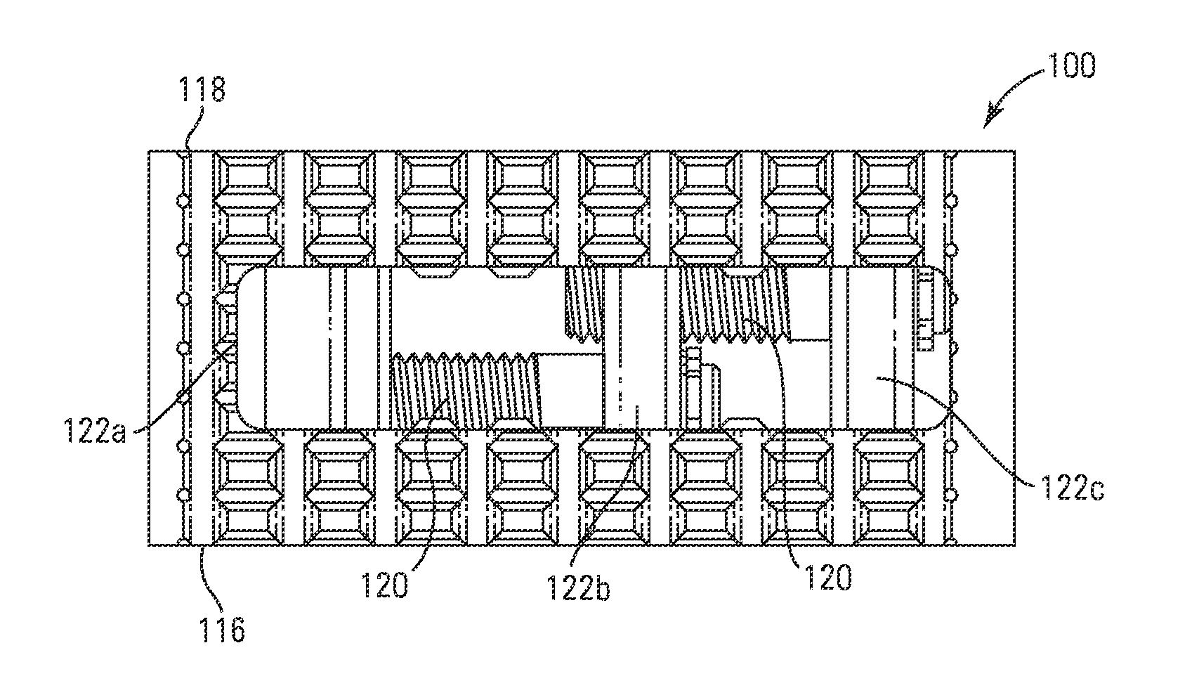
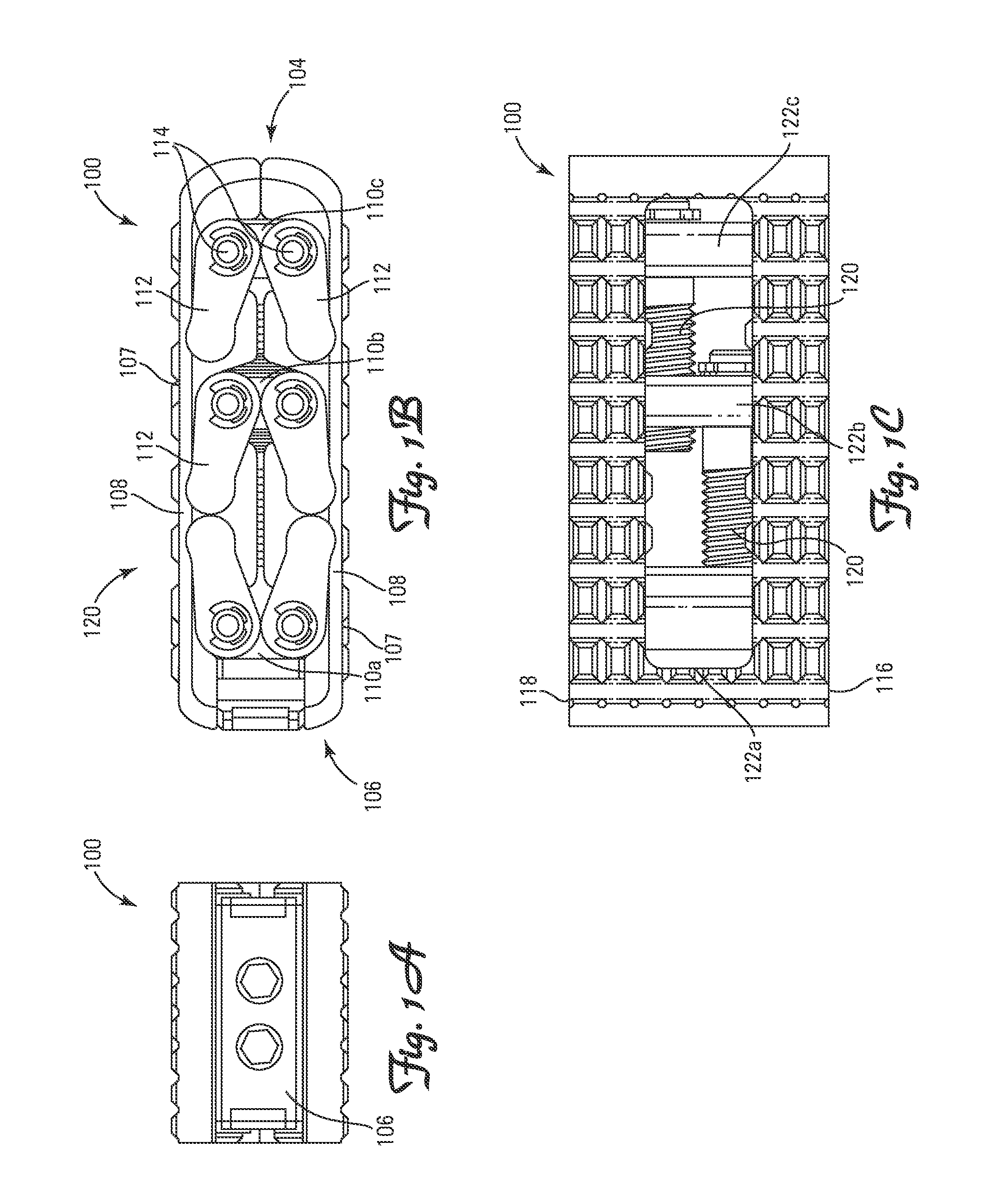
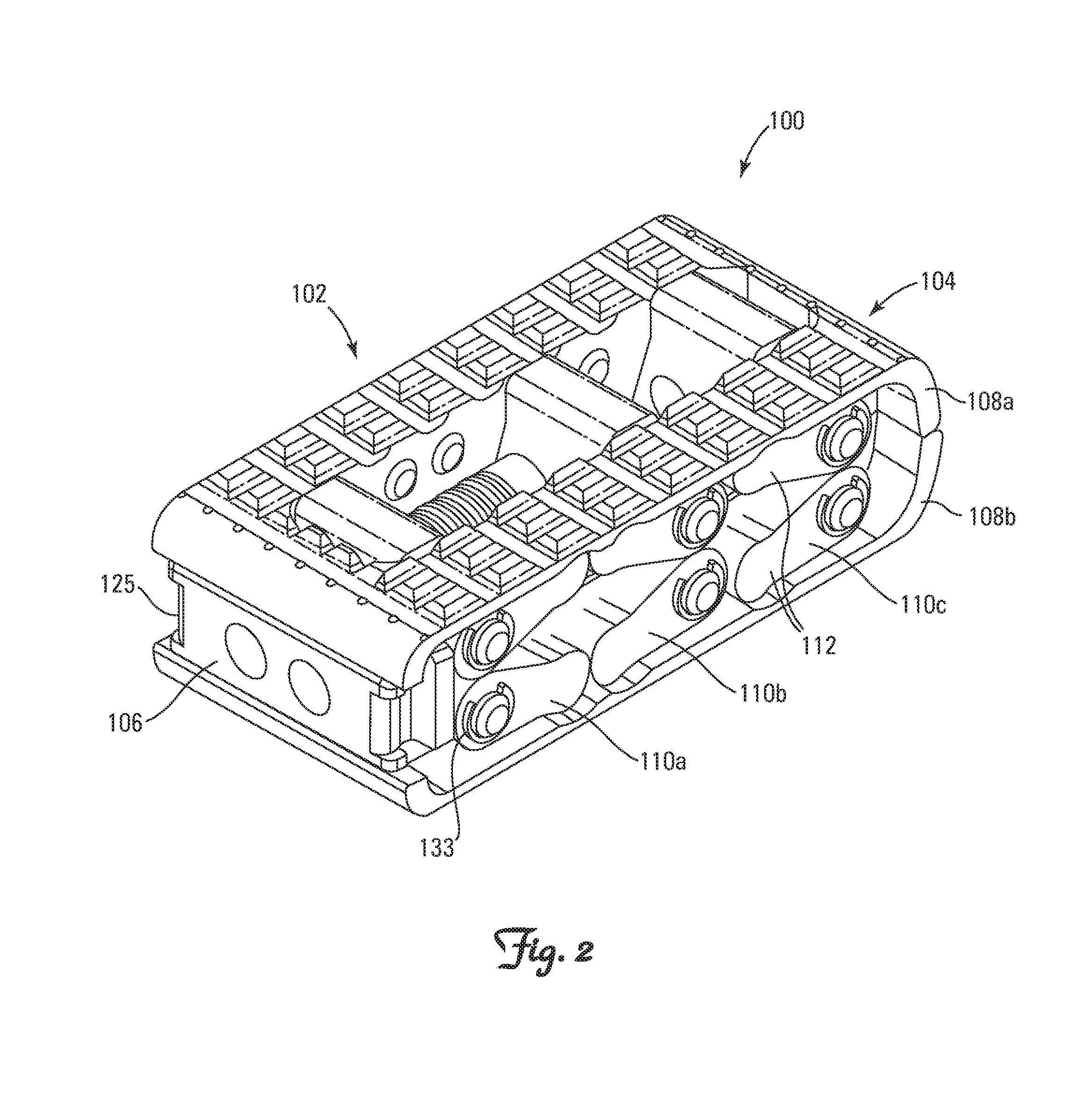
[0034]Referring to FIGS. 1A-1C and FIG. 2, there can be seen an expandable intervertebral cage device 100 according to an aspect of the present invention. Device 100 includes a device body 102. Device body 102 ...


PUM


Abstract

An expandable intervertebral cage adapted to be implanted into an intervertebral disc space in a patient's body, the expandable intervertebral cage including first and second base plates having outer surfaces configured to interface with vertebra in the intervertebral disc space, a first, second and third arm assembly hingedly connected to first and second base plates, and first and second actuation members, wherein rotation of the first actuation member pulls the second arm assembly towards the first arm assembly and rotation of the second actuation member pulls the third arm assembly towards the second arm assembly, the first actuation member and the second actuation member capable of being actuated independently of each other.

Description

TECHNICAL FIELD[0001]The present invention relates to the distraction and fusion of vertebral bodies. More specifically, the present invention relates to devices and associated methods for distraction and fusion of vertebral bodies that remain stable when implanted and facilitate fusion following their use for distraction to aid in the correction of spinal deformity by reducing a collapsed disc and establishing sagittal alignment, lordosis, or kyphosis.BACKGROUND[0002]The concept of intervertebral fusion for the cervical and lumbar spine following a discectomy was generally introduced in the 1960s. It involved coring out a bone graft from the hip and implanting the graft into the disc space. The disc space was prepared by coring out the space to match the implant. The advantages of this concept were that it provided a large surface area of bone to bone contact and placed the graft under loading forces that allowed osteoconduction and induction enhancing bone fusion. However, the tec...

Claims


Application Information

Patent Timeline
IPC IPC(8): A61F2/44
CPCA61F2/447A61F2002/30471A61F2002/30507A61F2002/30538A61F2002/30556
Inventor JIMENEZ, OMAR F.SAFRIS, YEFIM
Owner SPINEX TEC
Learn More