Method for operating a wind turbine having a rotor hub supporting at least one rotor blade

a technology of rotor blades and wind turbines, which is applied in the direction of electric generator control, process and machine control, instruments, etc., can solve the problems of reducing the power production of the wind turbine, affecting the aerodynamic performance of the rotor blades, and the inability to achieve specific rated power production

Active Publication Date: 2015-01-27
SIEMENS GAMESA RENEWABLE ENERGY AS
View PDF12 Cites 6 Cited by
  • Summary
  • Abstract
  • Description
  • Claims
  • Application Information

AI Technical Summary

Benefits of technology

[0008]An improved method for operating a wind turbine assuring proper operation of the wind turbine even when the aerodynamic performance of the rotor blades is negatively influenced, particularly due to ice at least partially covering at least one rotor blade is provided.
[0043]Thereby, the inventive principle is based on the notion to adaptively adjust the speed-power-curve or speed-torque-curve or speed-power-relation or speed-torque-relation of the wind turbine. This may be done by scaling, i.e. lowering or raising the respective power values defined in the respective currently applied first control rule, i.e. by changing the control rule. By concertedly reducing the power values by scaling them down with a certain scaling factor, less power has to be supplied to the respective electrical converter units, i.e. the generator of the wind turbine will require less torque resulting in—under the premise of a constant wind speed—an increase of the rotational speed of the rotor hub since a certain fraction of rotational speed and / or torque, respectively is not used required for operating the generator. As a consequence, the rotational speed of the wind turbine may increase after a certain time, which may lead to an increase of the effective power output of the wind turbine.
[0045]Thereby, it is possible to compare a number of respective control rules and respective power outputs obtained or obtainable by applying the respective control rules before in fact applying a respective second control rule for further operation of the wind turbine, whereby the further operation of the wind turbine is based on the respective control rule leading to the most effective power output of the wind turbine. Thereby, the application of averaging methods, particularly concerning the average power output obtained or obtainable by applying respective second control rules, may be of advantage.
[0051]The second control rule may be chosen under the premise that an increase of rotational speed of the rotor hub is obtained. In other words, the second control rule may be chosen in such a manner that the power values, i.e. the power demand of the generator of the wind turbine are reduced, i.e. the generator will require less power at a given rotational speed and / or wind speed. Hence, the tendency of stalling of the frosted rotor blades may be reduced or even overcome.
[0055]As has been mentioned, respective power values defined in respective speed-power-curves, speed-torque-curves, etc. underlying respective second control rules may be lower in comparison to respective power output values defined in respective speed-power-curves underlying respective first control rules. In such a manner, the operation of the generator on basis of a respective second control rule will require less torque for a given rotational speed such that the rotational speed of the rotor hub will increase since the wind turbine has to deliver less power for the same rotational speed of the rotor hub than before, i.e. when assuming constant wind speed and operating the wind turbine on basis of the first control rule. In such a manner, it is possible that the effective power output of the wind turbine on basis of the second control rule may be equal or even exceed the power output of the wind turbine on basis of the first control rule which is mainly based on the fact that the rotational speed of the rotor hub based on the second control rule is higher in comparison to the rotational speed of the rotor hub based on the first control rule.
[0058]Hence, at temperatures far below 0° C., it may be necessary to change the control rule of the wind turbine more frequently in order to obtain an optimised operation of the wind turbine correlated to an optimised power output of the wind turbine since the formation as well as the amount of ice on the rotor blades is usually increased at temperatures far below 0° C. in comparison to temperatures ranging in the region of 0° C. Hence, the ambient temperature may be used as an indicator of how often and / or how fast choosing and applying a second control rule may be executed in order to assure an optimal power output of the wind turbine.

Problems solved by technology

It is known that changes of the aerodynamic performance or properties of the rotor blades of a wind turbine may both impact the performance of the rotor hub and change the optimal control rule usually embracing a number of control settings, operational parameters, etc., and may consequently lead to a decrease of the power production of the wind turbine.
Thus, a wind turbine will operate suboptimal and a specific rated power production may not be reached in this case.
The aerodynamic performance of the rotor blades is mainly negatively influenced due to specific climatic conditions such as temperature, humidity etc. which may lead to the formation of ice at least partially covering the surface of the rotor blades.
This problem usually occurs during winter.
Thereby, it is a problem that rotor blades being at least partially covered with ice usually tend to stall due to the weight and shape of the ice and / or because the currently control rule typically assuming blades free of ice is no longer appropriate or suitable, which usually leads to a significant decrease of the power output of the wind turbine.
Further, icy or frosted rotor blades may also encounter high mechanical loads as well as thrust.
However, in the case of the rotor blades being at least partially covered with ice and hence differ in their aerodynamic performance, proper operation and / or control rules or strategies of wind turbines are usually not available.

Method used


Image

  • Method for operating a wind turbine having a rotor hub supporting at least one rotor blade
  • Method for operating a wind turbine having a rotor hub supporting at least one rotor blade
  • Method for operating a wind turbine having a rotor hub supporting at least one rotor blade

Examples


Embodiment Construction

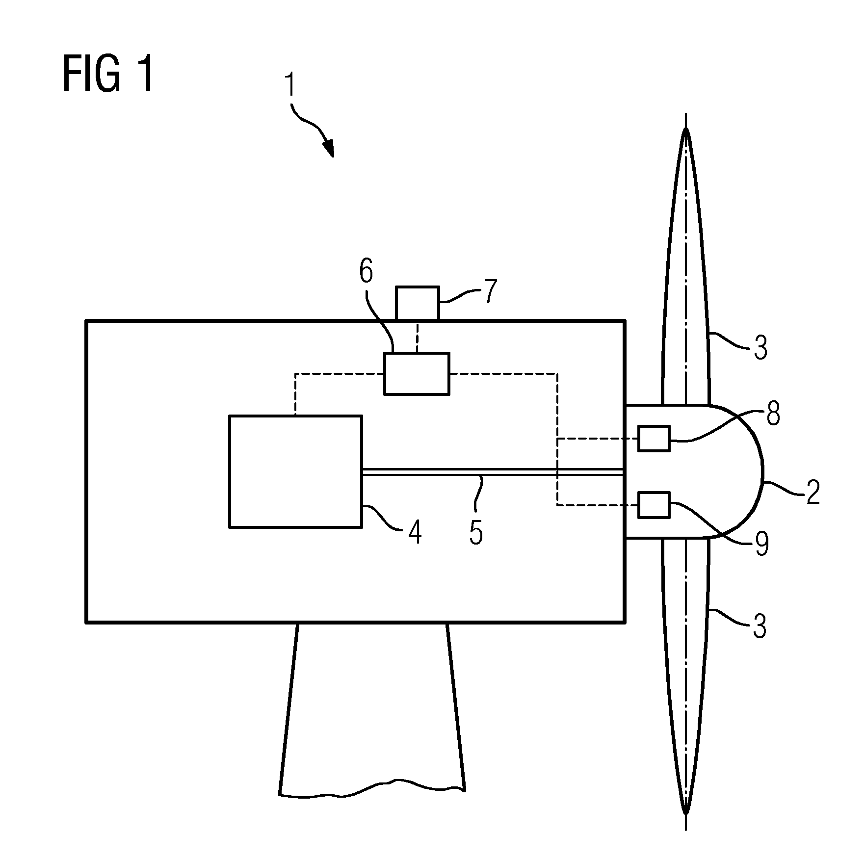
[0071]FIG. 1 shows a principle drawing of a wind turbine 1 according to an exemplary embodiment of the invention. The wind turbine 1 comprises a rotor hub 2 supporting a number of rotor blades 3 with the rotor blades 3 being pitchable around their longitudinal axes by an appropriate rotor blade pitching means (not shown). The wind turbine 1 is a direct-drive wind turbine, i.e. the rotor hub 2 is directly coupled to a generator 4 by means of a main shaft 5. Yet, the provision of a gear box interposed between the rotor hub 2 and the generator 4 is not obligatory, but in principle possible.

[0072]Further, a control unit 6 in terms of a central wind turbine controller is provided which control unit 6 communicates with the generator 4 and respective sensor means provided with the wind turbine 1, i.e. a climatic sensor 7 providing climatic information regarding the climatic conditions in the region of the wind turbine 1 such as information relating to ambient temperature and / or ambient pre...


PUM


Abstract

A method for operating a wind turbine which includes a rotor hub supporting a rotor blade includes: a) detecting changes in the aerodynamic performance of the rotor blade; b) determining a first control rule; c) determining a first power output information indicating a first power output based on the first control rule; d) changing an operational parameter and choosing a second control rule such that the first control rule is replaced by the second control rule; e) determining a second power output information indicating a second power output based on the second control rule. c) comparing the first and second power output information. If the second power output exceeds the first power output, repeating a)-f) with the second control rule being used as the first control rule in b); otherwise repeating a)-f) a different second control rule is applied in d).

Description

CROSS REFERENCE TO RELATED APPLICATIONS[0001]This application claims priority of European Patent Office application No. 12163152.7.3 EP filed Apr. 4, 2012. All of the applications are incorporated by reference herein in their entirety.FIELD OF INVENTION[0002]The disclosure relates to a method for operating a wind turbine having a rotor hub supporting at least one rotor blade.BACKGROUND OF INVENTION[0003]It is known that changes of the aerodynamic performance or properties of the rotor blades of a wind turbine may both impact the performance of the rotor hub and change the optimal control rule usually embracing a number of control settings, operational parameters, etc., and may consequently lead to a decrease of the power production of the wind turbine. Thus, a wind turbine will operate suboptimal and a specific rated power production may not be reached in this case.[0004]The aerodynamic performance of the rotor blades is mainly negatively influenced due to specific climatic conditio...

Claims


Application Information

Patent Timeline
Patent Type & Authority Patents(United States)
IPC IPC(8): F03D7/04F03D7/02F03D11/00
CPCF03D7/04F03D7/046F03D11/0025F03D7/02Y02E10/722Y02E10/723F03D80/40Y02E10/72
Inventor CHRISTIANSEN, PER MOELHAVEESBENSEN, THOMASLAURBERG, HANSRIEPER, JOHNNY
Owner SIEMENS GAMESA RENEWABLE ENERGY AS
Why Eureka
Try Eureka