Logic circuit device comprising at least one digital input

a logic circuit and digital input technology, applied in the direction of instruments, computations using denominational number representation, pulse techniques, etc., can solve the problems of complex and expensive techniques, long time-consuming, expensive and constraining, etc., and achieve the effect of less expensive and easier implementation

Inactive Publication Date: 2015-01-27
THALES SA
View PDF6 Cites 0 Cited by
  • Summary
  • Abstract
  • Description
  • Claims
  • Application Information

AI Technical Summary

Benefits of technology

[0013]An aim of the invention is to propose a device which is less expensive and easier to implement.

Problems solved by technology

It is also known to electrically link two surfaces electrically insulated from one another with conducting wires but this technique is complex and expensive.
But all these solutions require physical intervention on the electronic card, this often being lengthy, expensive and constraining.

Method used


Image

  • Logic circuit device comprising at least one digital input
  • Logic circuit device comprising at least one digital input
  • Logic circuit device comprising at least one digital input

Examples


Embodiment Construction

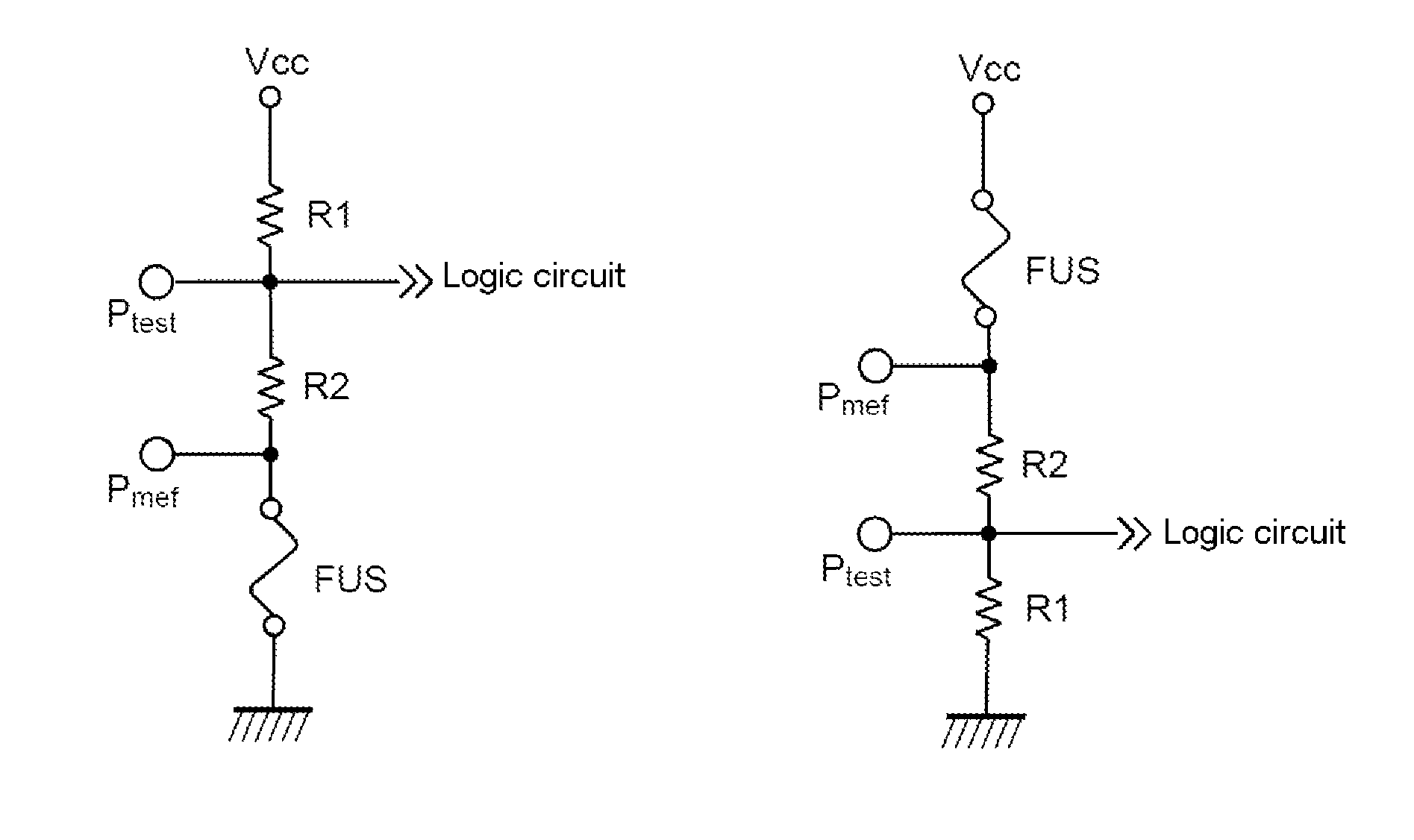
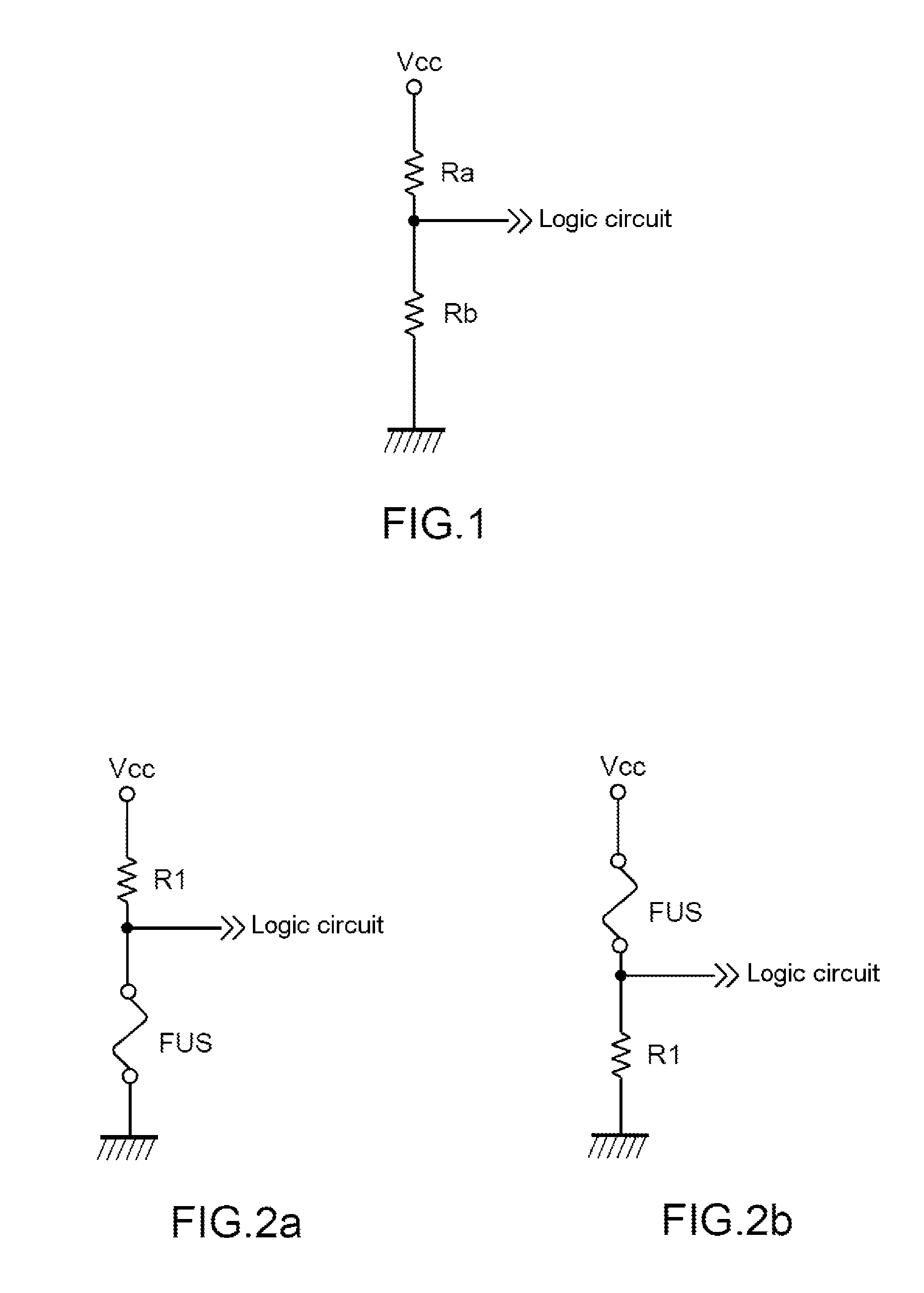
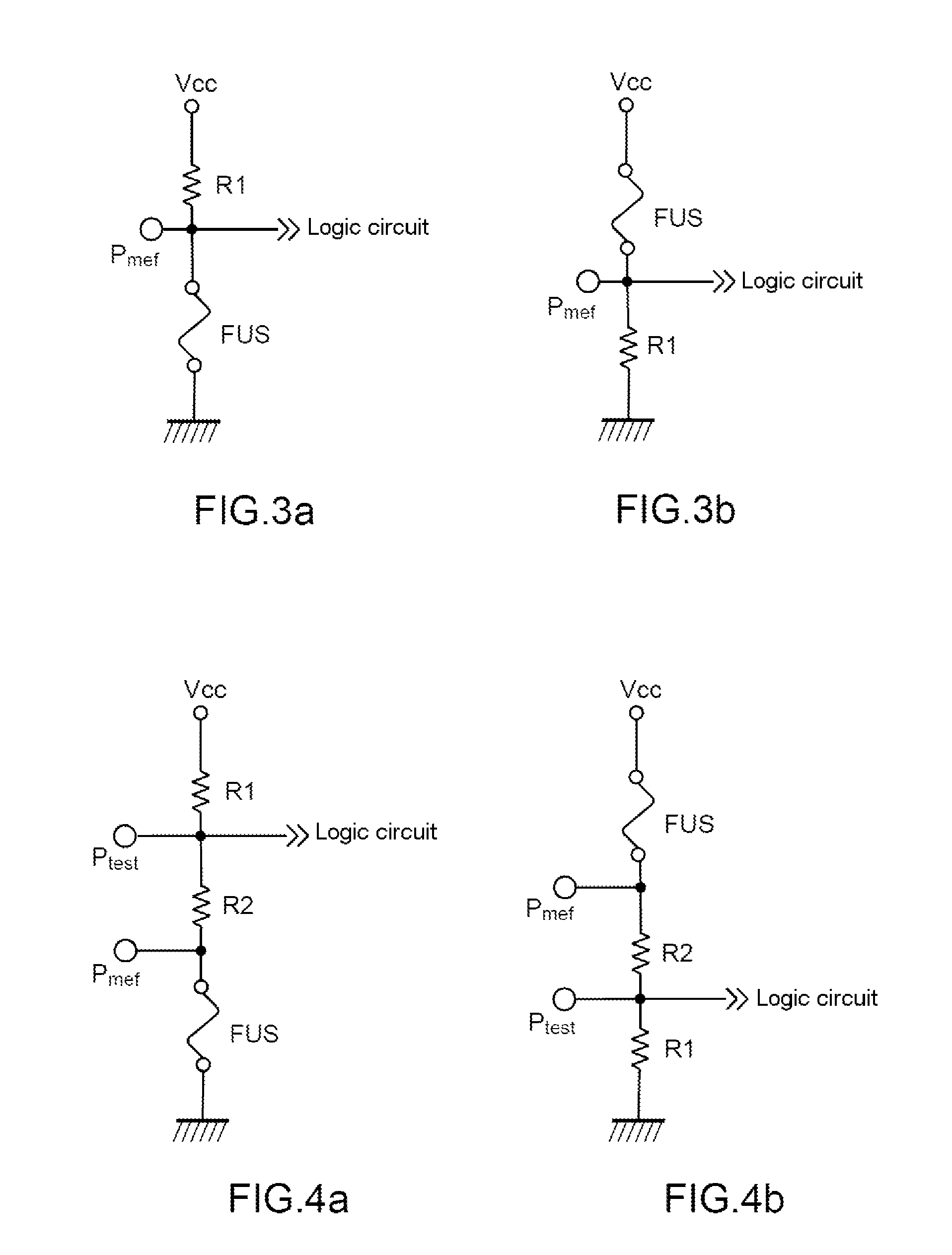
[0039]As illustrated in FIG. 2a, the logic circuit device comprises at least one digital input, in this instance one, furnished with a fuse FUS, connected electrically at a first end to earth. The fuse FUS is, in the closed state, suitable for allowing an electrical input voltage of the logic circuit corresponding to a 0 logic state, and, in the definitive open state, suitable for allowing an electrical input voltage of the logic circuit corresponding to a 1 logic state. The fuse FUS is suitable for being placed definitively in the open state by injection of a current greater than a threshold current CS, making it toggle to the definitive open state.

[0040]The digital input comprises, furthermore, a first resistor R1 for maintaining the electrical input potential at an electrical potential corresponding to the 1 logic state, disposed between a second end of the fuse FUS and a first electrical input point Vcc for powering the logic circuit.

[0041]As illustrated in FIG. 2b, as a variant...


PUM


Abstract

The invention pertains to a logic circuit device comprising at least one digital input furnished with a fuse (FUS) being, in the closed state, suitable for applying an electrical input voltage of the logic circuit corresponding to a first logic state from among the logic states 0 and 1, and, in the definitive open state, suitable for applying an electrical input voltage of the logic circuit corresponding to the second logic state from among the logic states 0 and 1, said fuse (FUS) being suitable for being placed definitively in the second logic state by injection of a current greater than a threshold current (CS).

Description

BACKGROUND OF THE INVENTION[0001]1. Field of the Invention[0002]The present invention pertains to a logic circuit device comprising at least one digital input.[0003]2. Description of the Related Art[0004]Logic circuits comprising at least one digital input, such as Application-Specific Integrated Circuits (ASICs), are known.[0005]Systems making it possible to fix a logic level in an unalterable manner on a digital input are known.[0006]For example, it is possible to fix the inputs of a logic circuit by hard-wiring, with two resistors, and by wiring up either one or the other the logic level is modified. In this case, the inputs are determined before assembling the electronic card, and the mounted components define the logic levels.[0007]FIG. 1 illustrates such an embodiment, in which two resistors Ra and Rb, for example of the order of 100 kΩ, and Vcc represents the electrical power supply for the device.[0008]Such an implementation is constraining, since the parameters to be progra...

Claims


Application Information

Patent Timeline
Patent Type & Authority Patents(United States)
IPC IPC(8): H01H37/76H03K19/003H03K19/173
CPCH03K19/00346H03K19/1733
Inventor ROCHAS, VINCENT
Owner THALES SA
Why Eureka
Try Eureka