Array of luminescent elements

a luminescent element and array technology, applied in the field of light emitting systems, can solve the problems of increasing the size and power consumption of optical systems that employ optical systems, inefficient current leds, and especially green-emitting leds

Inactive Publication Date: 2015-01-27
3M INNOVATIVE PROPERTIES CO
View PDF45 Cites 31 Cited by
  • Summary
  • Abstract
  • Description
  • Claims
  • Application Information

AI Technical Summary

Benefits of technology

[0015]In another embodiment, a light emitting system includes a first luminescent element capable of outputting light at a first wavelength; and a second luminescent element capable of outputting light at a second wavelength different from the first wavelength. The second luminescent element includes an electroluminescent device capable of emitting light at the first wavelength; a first light converting element for converting at least a portion of light emitted by the electroluminescent device from the first wavelength to a third wavelength different from the first and second wavelengths; and a second light converting element for converting at least a portion of light converted by the first light converting element from the third wavelength to the second wavelength.

Problems solved by technology

Current LEDs, however, especially green emitting LEDs, are relatively inefficient.
Conventional light sources are generally bulky, inefficient in emitting one or primary colors, difficult to integrate, and tend to result in increased size and power consumption in optical systems that employ them.

Method used


Image

  • Array of luminescent elements
  • Array of luminescent elements
  • Array of luminescent elements

Examples


Embodiment Construction

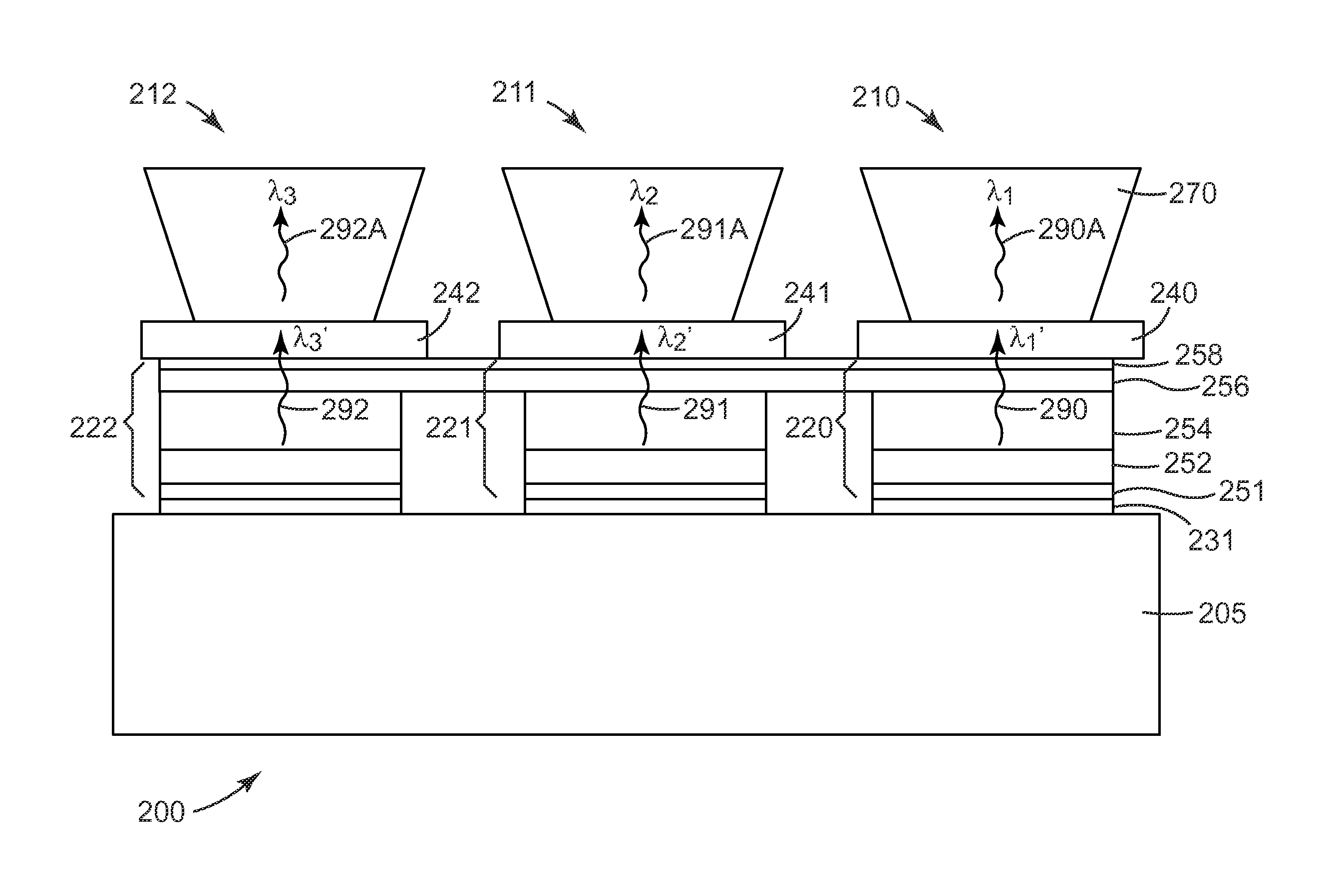
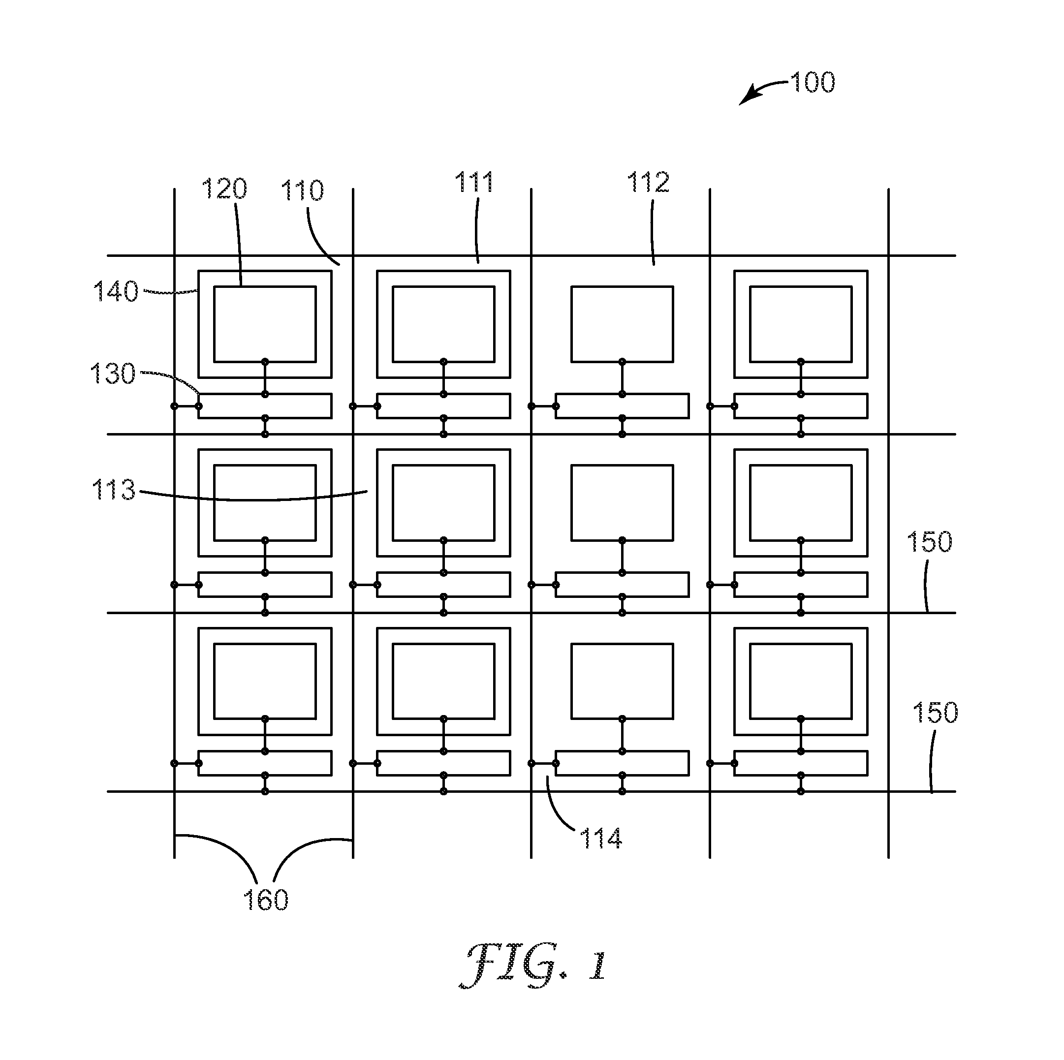
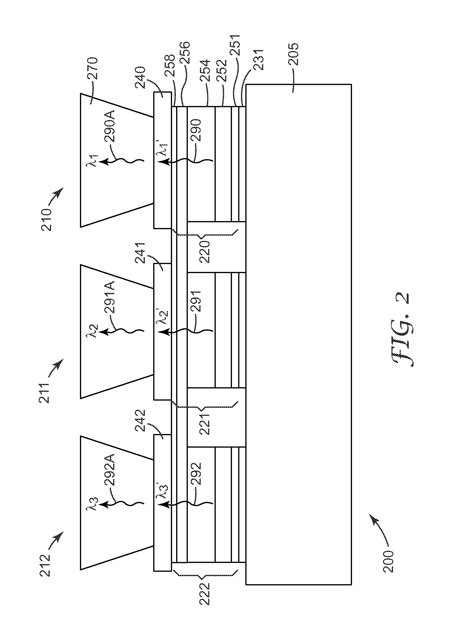
[0032]This application teaches light sources that include an array of light emitting regions. The disclosed light sources can efficiently output light at any wavelength in, for example, the visible region of the spectrum. The light sources can be designed to output, for example, one or more primary colors or white light. The light sources can be compact with reduced weight because, for example, the array of light emitting regions can be compactly integrated onto a substrate. The emission efficiency and compactness of the disclosed light sources can lead to new and improved optical systems, such as portable projection systems, with reduced weight, size and power consumption.

[0033]The disclosed light sources can have larger and smaller light emitting regions where the output light of each region can be actively and independently controlled. The light sources can be used in, for example, a projection system to illuminate one or more pixelated image forming devices. Each light emitting ...


PUM


Abstract

Light emitting systems and method of fabricating the same are disclosed. The light emitting system includes two or more monolithically integrated luminescent elements. Each luminescent element includes an electroluminescent device and a dedicated switching circuit for driving the electroluminescent device. At least one luminescent element includes a potential well for down converting light emitted by the electroluminescent device in the luminescent element.

Description

FIELD OF THE INVENTION[0001]This invention generally relates to light emitting systems. The invention is particularly applicable to light emitting systems having two or more light emitting regions.BACKGROUND[0002]Illumination systems are used in many different applications, including projection display systems, backlights for liquid crystal displays and the like. Projection systems typically use one or more white light sources, such as high pressure mercury lamps. The white light beam is usually split into three primary colors, red, green and blue, and is directed to respective image forming spatial light modulators to produce an image for each primary color. The resulting primary-color image beams are combined and projected onto a projection screen for viewing.[0003]More recently, light emitting diodes (LEDs) have been considered as an alternative to white light sources. LEDs have the potential to provide the brightness and operational lifetime that would compete with conventional ...

Claims


Application Information

Patent Timeline
Patent Type & Authority Patents(United States)
IPC IPC(8): G09G3/32G09G3/30H01L27/15H05B44/00
CPCH01L27/156F21Y2105/10F21Y2115/10F21S41/18F21S41/255F21S41/43F21S41/645F21S41/663H01L33/08H01L27/124H01L27/1255H01L33/28H01L33/58
Inventor HAASE, MICHAEL A.
Owner 3M INNOVATIVE PROPERTIES CO
Why Eureka
Try Eureka