Seal structure for electronic control device

a technology of electronic control device and sealing structure, which is applied in the direction of gaseous cathodes, hermetically sealed casings, electric apparatus casings/cabinets/drawers, etc., can solve the problem of difficult to ensure the sealing performan

Inactive Publication Date: 2015-01-27
HITACHI AUTOMOTIVE SYST LTD
View PDF12 Cites 42 Cited by
  • Summary
  • Abstract
  • Description
  • Claims
  • Application Information

AI Technical Summary

Benefits of technology

[0004]It is therefore an object of the present invention to provide a seal structure for the electronic control device, which is capable of ensuring the sealing performance of the merged part of the two seal portions.

Problems solved by technology

In this case, however, since a seal structure of this merged part is a so-called three-way seal structure in which the two seal portions, both of which are an endless extending ring-shaped seal portion, meet or cross at this merged part, it is difficult to ensure the sealing performance.

Method used


Image

  • Seal structure for electronic control device
  • Seal structure for electronic control device
  • Seal structure for electronic control device

Examples


Embodiment Construction

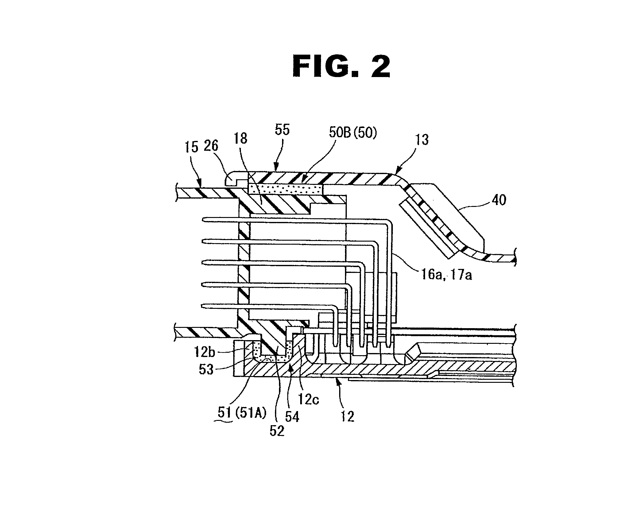
[0020]According to the present invention, besides providing a normal seal groove and a normal protruding line, an auxiliary seal groove and an auxiliary protruding line are provided at a merged part where two seal portions meet, and a gap between these auxiliary seal groove and auxiliary protruding line is filled with a sealant. It is therefore possible to secure an equivalent seal length by the same quantity of sealant as that of a normal seal portion, and decrease of the sealing performance of this merged part can be suppressed or avoided.

[0021]Embodiments of a seal structure for the electronic control device of the present invention will now be explained below with reference to the drawings.

[0022]In the following description, a case where the seal structure for the electronic control device is employed in an engine control unit of a vehicle will be explained in detail.

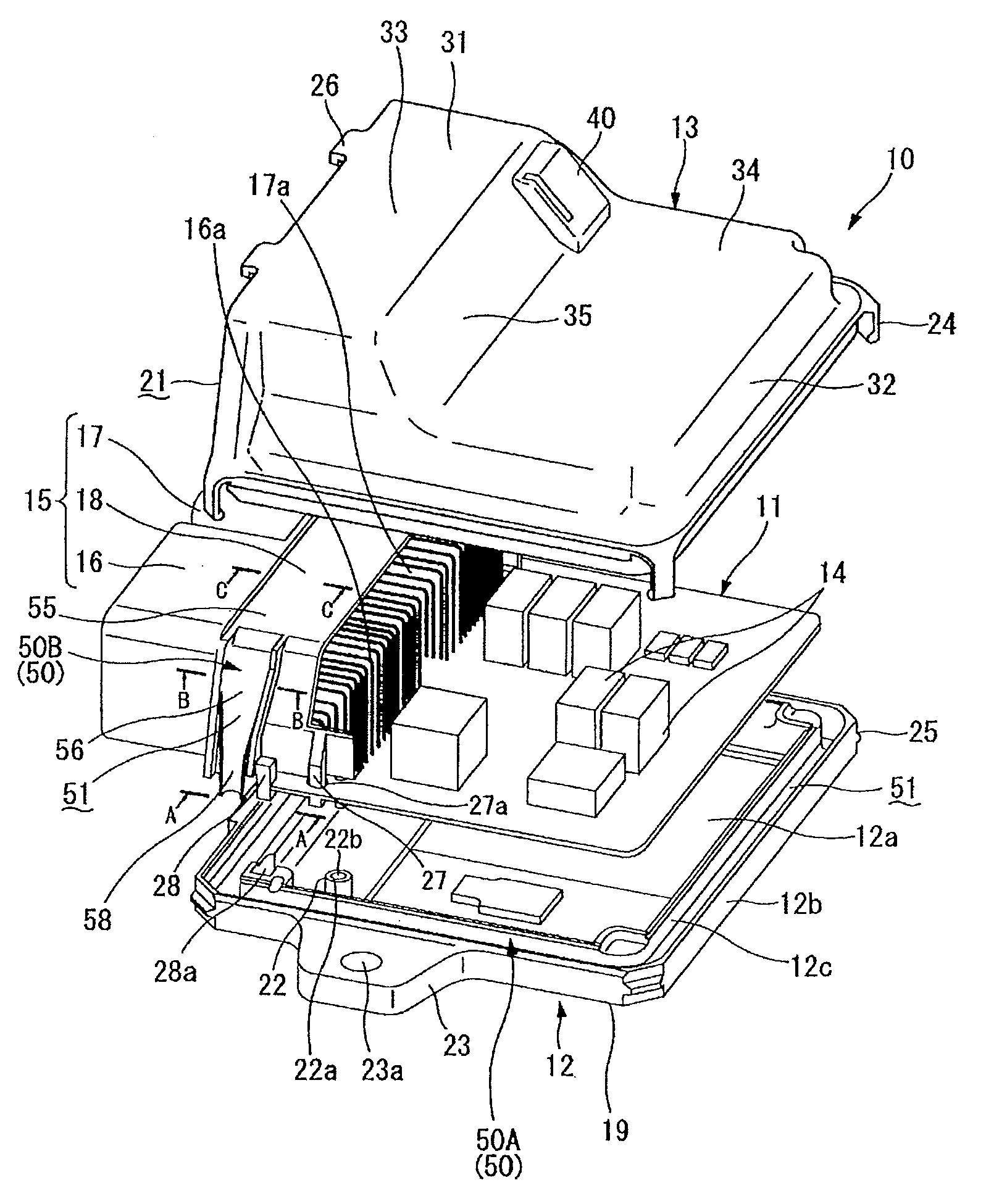
[0023]First, a basic configuration of an electronic control device 10 will be explained with reference to FIGS. 1...


PUM


Abstract

A seal structure for an electronic control device having a circuit board housed in a watertight space a housing that is formed by fitting a plurality of fitting members together, has first and second seal portions which are formed at a fitting surface portion between the fitting members that are fitted together. One side of a pair of the fitting members of each of the first and second seal portions is provided with a seal groove, the other side is provided with a protruding line. An auxiliary seal groove and an auxiliary protruding line are formed on opposing surfaces of the seal groove and the protruding line at a merged part where the first and second seal portions meet each other. The auxiliary seal groove and the auxiliary protruding line continuously extend from the seal groove up to an end surface of the protruding line.

Description

BACKGROUND OF THE INVENTION[0001]The present invention relates to a seal structure for an electronic control device, which is favorable for an engine control unit or an automatic transmission control unit.[0002]As an example of the seal structure for the electronic control device, it is disclosed in Japanese Patent Provisional Publication No. 2009-070855 (hereinafter is referred to as “JP2009-070855”). In JP2009-070855, the seal structure of a so-called connector-side-mounted type of electronic control device, in which a part of the connector fixed to one side of a circuit board is exposed to an outside of a casing from a window of the casing, is disclosed. Both upper and lower surfaces of the connector are sandwiched between and by a pair of connector sandwiching members of the casing from width direction of the circuit board. A casing seal portion, which is filled with a sealing material, is provided at a fitting surface portion between periphery edge portions of the pair of conne...

Claims


Application Information

Patent Timeline
Patent Type & Authority Patents(United States)
IPC IPC(8): H05K5/06H05K5/00
CPCH05K5/0052H05K5/0069H05K5/062
Inventor KAWAI, YOSHIOYANAGISAWA, YUICHIOHHASHI, HIRONORI
Owner HITACHI AUTOMOTIVE SYST LTD
Why Eureka
Try Eureka