Lens device and position detection method of movable optical element

a technology of optical elements and position detection methods, which is applied in the field of optical lens devices and position detection methods of movable optical elements, can solve the problems of unevenness of magnetic signals, and easy generation of unevenness in recorded magnetic signals, and achieves simplified configuration, high precision, and low cost

Active Publication Date: 2015-01-27
FUJIFILM CORP
View PDF13 Cites 0 Cited by
  • Summary
  • Abstract
  • Description
  • Claims
  • Application Information

AI Technical Summary

Benefits of technology

[0011]However, when the annular magnetic recording medium is formed in a hollow shape, unevenness may be easily generated in a recorded magnetic signal. The unevenness is specifically significant in a lens device having a large lens aperture such as a lens device for a television broadcast or movie. Further, since a gap between the lens device and other members is small in consideration of small size and light weight, an insertion error occurs when the position detector using the annular magnetic recording media is inserted in the lens device, which may also cause the unevenness of the magnetic signal.
[0015]According to the position detector disclosed in Patent Literature 3, even though precision of detecting the absolute position is increased, a plurality of MR sensors is required for each of the annular magnetic recording media, which may increase a manufacturing cost and a size of the lens device.
[0016]In view of above, an illustrative aspect of the present invention is to provide a lens device and a method of detecting a position of a movable optical element which are capable of detecting an absolute position of the movable optical element with low cost, simplified configuration, and high precision.
[0019]With any of the configurations discussed above, it is possible to provide a lens device and a position detection method of a movable optical element which are capable of detecting an absolute position of the movable optical element with low cost, simplified configuration, and high precision.

Problems solved by technology

However, when the annular magnetic recording medium is formed in a hollow shape, unevenness may be easily generated in a recorded magnetic signal.
The unevenness is specifically significant in a lens device having a large lens aperture such as a lens device for a television broadcast or movie.
Further, since a gap between the lens device and other members is small in consideration of small size and light weight, an insertion error occurs when the position detector using the annular magnetic recording media is inserted in the lens device, which may also cause the unevenness of the magnetic signal.
When the above-mentioned unevenness is generated in the magnetic signal, the phase difference which is calculated from the output signals of the two MR sensors is shifted from a design value, and thus, it is difficult to precisely detect the absolute position of the lens.

Method used


Image

  • Lens device and position detection method of movable optical element
  • Lens device and position detection method of movable optical element
  • Lens device and position detection method of movable optical element

Examples


Embodiment Construction

[0029]Hereinafter, an exemplary embodiment of the present invention will be described with reference to the drawings.

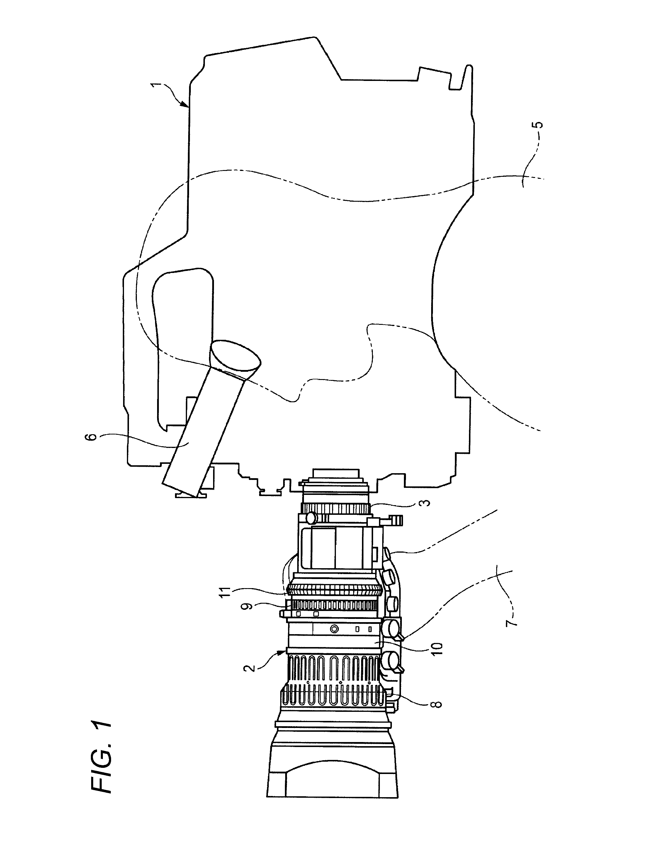
[0030]FIG. 1 is an external view of an imaging device which is mounted with a lens device 2 according to an exemplary embodiment of the present invention. The lens device 2 is mounted on a front side of a main body of an imaging device 1.

[0031]The lens device 2 includes a case 10 having a tubular shape such as a cylindrical shape. In the case 10, an imaging lens such as a zoom lens or a focus lens and a diaphragm device which is capable of adjusting an aperture amount are mounted therein. A mount unit 3 is formed in a base unit of the case 10 of the lens device 2. A connecting unit of the mount unit 3 is detachably mounted to a lens installation unit which is provided on the front side of the main body of the imaging device 1 so that the lens device 2 is fixed to the main body of the imaging device 1.

[0032]In the main body of the imaging device 1, an imaging element i...


PUM

PropertyMeasurementUnit
rotation angleaaaaaaaaaa
diametersaaaaaaaaaa

Abstract

A lens device includes a movable optical element, a rotary member; first and second magnetic recording scales fixedly disposed on an outer periphery of the rotary member to extend along a peripheral direction of the rotary member; a signal detecting unit which detects first to fourth signals; and a position detecting unit which detects a position of the movable optical element based on the detected signals, in which the position detecting unit includes: a phase difference calculating unit which calculates a phase difference between the first signal and the third signal, based on the detected first to fourth signals for one cycle; a phase average calculating unit which calculates an average of the phase differences respectively calculated for n cycles; and an absolute position detecting unit which detects an absolute position of the movable optical element based on the calculated average.

Description

CROSS REFERENCE TO RELATED APPLICATION[0001]This is a continuation of International Application No. PCT / JP2012 / 079699 filed on Nov. 15, 2012, and claims priority from Japanese Patent Application No. 2012-016971, filed on Jan. 30, 2012, the entire disclosures of which are incorporated herein by reference.BACKGROUND[0002]1. Technical Field[0003]The present invention relates to a lens device which is suitable for broadcast or a movie and a position detection method of a movable optical element which is mounted in the lens device.[0004]2. Related Art[0005]Recently, as a large screen size and high definition of a television or a monitor has progressed, a demand on a high quality of an image to be projected is increased. In order to satisfy the demand on the high quality image, a position detector which detects a position with high precision is mounted in a zoom lens for a movie or broadcast to increase the performance of lens control.[0006]While not for a lens device, a position detector...

Claims


Application Information

Patent Timeline
Patent Type & Authority Patents(United States)
IPC IPC(8): G03B17/00G11B5/008H04N5/238
CPCH04N5/238G11B5/00813G01B7/30G02B7/10G01D5/2452H04N23/75
Inventor MIYASHITA, MAMORU
Owner FUJIFILM CORP
Why Eureka
Try Eureka