
Methods of manufacturing piezoelectric element, liquid ejecting head, and ultrasonic transducer

a piezoelectric element and liquid ejector technology, applied in the direction of piezoelectric/electrostrictive transducers, transducer types, printing, etc., can solve the problems of easy formation of pinpoint unevenness, and damage to the piezoelectric layer. , the effect of reducing the damag

Active Publication Date: 2017-06-20
SEIKO EPSON CORP
View PDF4 Cites 0 Cited by
  • Summary
  • Abstract
  • Description
  • Claims
  • Application Information

AI Technical Summary

Benefits of technology

This patent text describes methods for manufacturing piezoelectric elements and liquid ejecting heads with reduced damage to the layers. The methods involve creating uneven surfaces on the piezoelectric layers using isotropic dry etching, which reduces the damage caused by etchants compared to wet etching. The methods also allow for easier formation of pinpoint unevenness in specific regions. Overall, the techniques described in the patent text improve the production of piezoelectric elements and liquid ejecting heads with improved quality.

Problems solved by technology

However, there is a problem in that the etchant damages the piezoelectric layer when wet etching is performed to form unevenness on the surface of the piezoelectric layer.
In addition, the problem occurs not only in the piezoelectric element used in a liquid ejecting head or an ultrasonic transducer but also in the piezoelectric element used in other devices.
Further, it is possible to easily form the pinpoint unevenness in a predetermined region compared to the case of performing wet etching.

Method used


Image

  • Methods of manufacturing piezoelectric element, liquid ejecting head, and ultrasonic transducer
  • Methods of manufacturing piezoelectric element, liquid ejecting head, and ultrasonic transducer
  • Methods of manufacturing piezoelectric element, liquid ejecting head, and ultrasonic transducer

Examples


embodiment 1

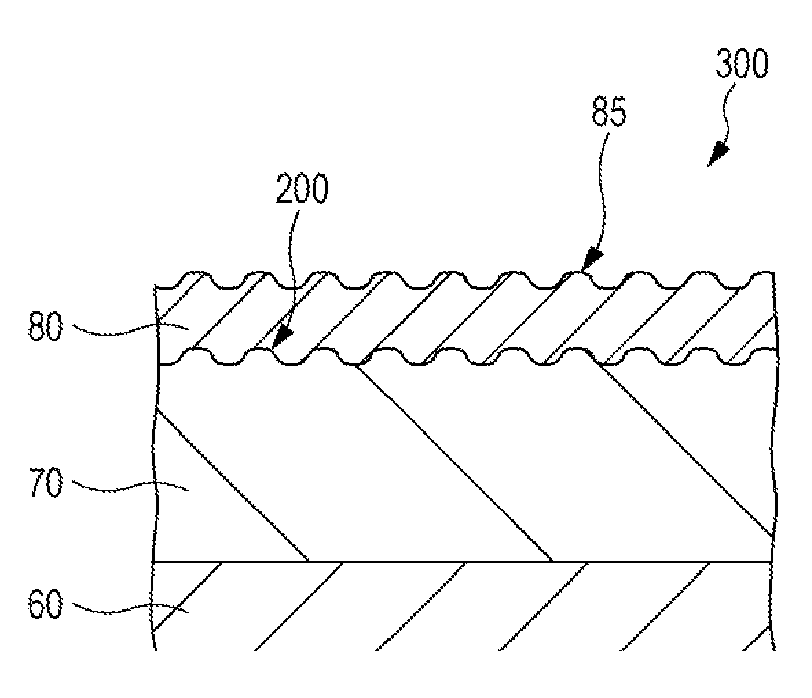
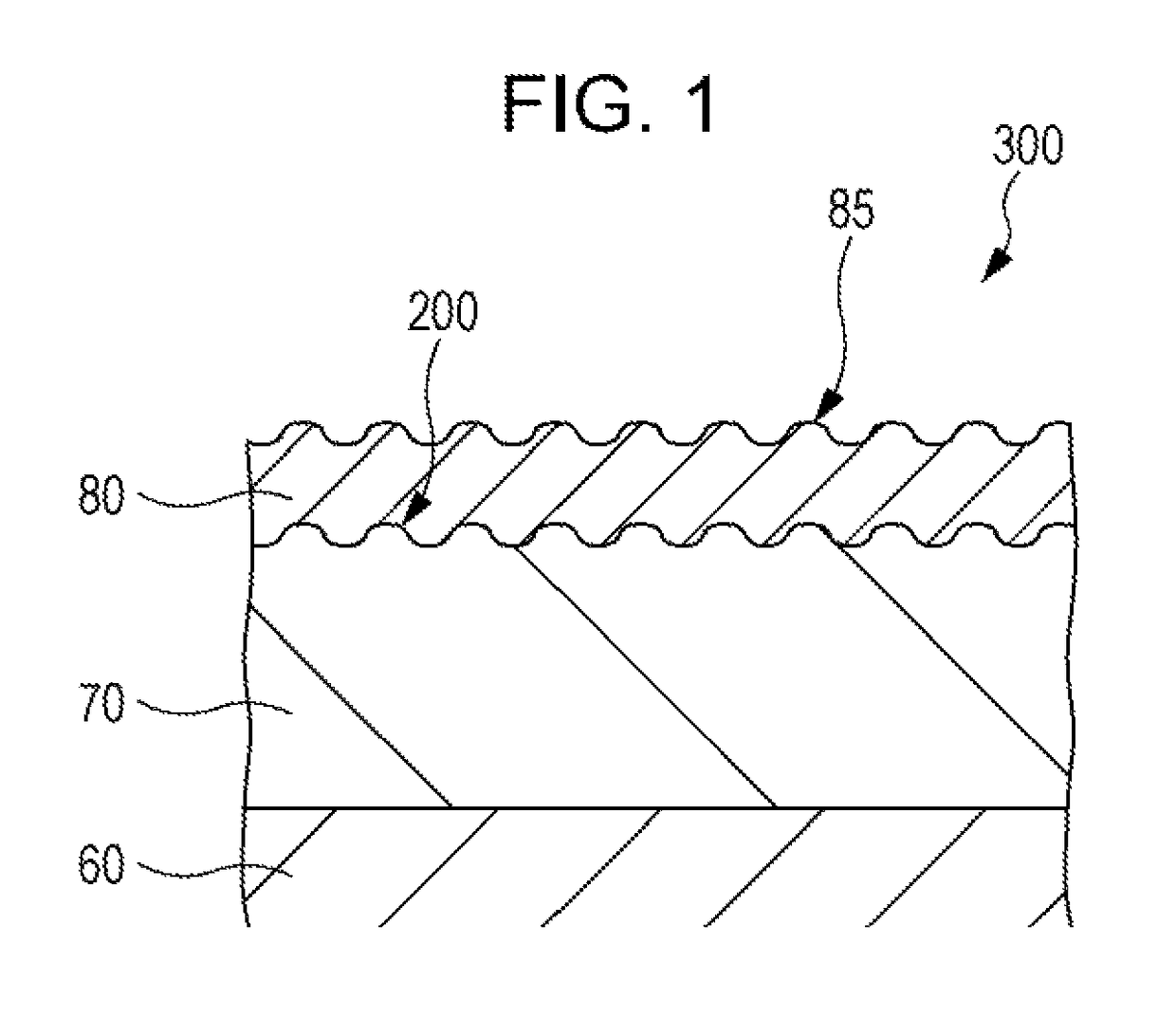
[0025]FIG. 1 is a cross-sectional view illustrating a piezoelectric element according to Embodiment 1 of the invention.

[0026]As illustrated in FIG. 1, a piezoelectric element 300 includes a first electrode 60, a piezoelectric layer 70, and a second electrode 80. According to the embodiment, although the embodiment is described with the first electrode 60 being provided on one side of the piezoelectric layer 70 and the second electrode 80 being provided on the other side of the piezoelectric layer 70, the invention is not limited thereto. For instance, the first electrodes 60 and the second electrodes 80 may be separately provided on one surface of the piezoelectric layer 70. In addition, the first electrodes 60 and the second electrodes 80 may be formed throughout the entire surface of the piezoelectric layer 70, or a portion thereof may be removed.

[0027]Here, the piezoelectric layer 70 is made of a piezoelectric material of an oxide having a polarization structure, for example, a c...

embodiment 2

[0043]FIG. 3 is an exploded perspective view illustrating an ink jet recording head which is an example of a liquid ejecting head according to Embodiment 2 of the invention. FIG. 4 is a cross-sectional view illustrating an ink jet recording head according to Embodiment 2. FIG. 5 is an enlarged view illustrating a main section of FIG. 4.

[0044]As illustrated, an ink jet recording head I (which is an example of a liquid ejecting head according to the embodiment) includes a plurality of members such as a head main body 9 and a case member 40, and the plurality of members are joined by a bonding agent or the like. According to the embodiment, the head main body 9 includes a channel forming substrate 10, a communication substrate 15, a nozzle plate 20, a protection substrate 30, and a compliance substrate 45.

[0045]In the channel forming substrate 10 configuring the head main body 9, pressure generating chambers 12 which are separated by a plurality of partitions are arranged in parallel b...

embodiment 3

[0075]Hereinafter, an ultrasonic sensor according to an embodiment of the invention is described. In addition, the embodiment described below is not intended to limit the invention recited in the claims, and not all the configurations of the embodiment are essential for the solution of the invention. Further, the same elements in the embodiment described above are denoted by the same reference numerals, and repeated description is omitted.

[0076]According to the embodiment, transmission and reception of ultrasonic waves are performed by using an electro-acoustic transducer using a piezoelectric effect. The electro-acoustic transducer is a piezoelectric element and uses conversion of electrical energy into mechanical energy (inverse piezoelectric effect) at the time of generating ultrasonic waves so that the change caused by contraction and expansion of the piezoelectric layer excites and vibrates the diaphragm such that ultrasonic waves are generated. Accordingly, in this case, the p...


PUM

PropertyMeasurementUnit
piezoelectricaaaaaaaaaa
pressure fluctuationaaaaaaaaaa
pressureaaaaaaaaaa

Abstract

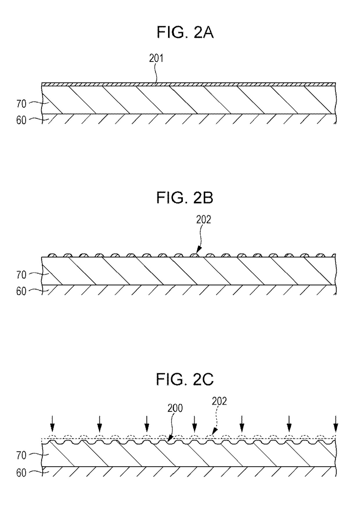
A method of manufacturing a piezoelectric element includes a first electrode, a piezoelectric layer, and a second electrode, in which unevenness on one surface of the piezoelectric layer is formed by forming an oxidizable metal layer on the one surface of the piezoelectric layer; aggregating the metal layer by thermal oxidation; and performing isotropic etching on the metal layer aggregated on the one surface of the piezoelectric layer.

Description

BACKGROUND[0001]1. Technical Field[0002]The present invention relates to a method of manufacturing a piezoelectric element (including a first electrode, a piezoelectric layer, and a second electrode), a method of manufacturing a liquid ejecting head, and a method of manufacturing an ultrasonic transducer.[0003]2. Related Art[0004]A known liquid ejecting head ejects liquid drops from nozzle openings communicating with pressure generating chambers by deforming a piezoelectric element (piezoelectric actuator) thereby causing pressure fluctuation in the liquid in the pressure generating chambers. A representative example of the liquid ejecting head is an ink jet recording head that ejects ink drops as liquid drops.[0005]The ink jet recording head, for example, includes a piezoelectric element on one surface of the channel forming substrate provided with the pressure generating chamber communicating with the nozzle opening. The ink jet recording head causes the pressure change in the liq...

Claims


Application Information

Patent Timeline
Patent Type & Authority Patents(United States)
IPC IPC(8): H01L41/22H01L41/332H01L41/09B41J2/16H04R17/00H01L41/08
CPCB41J2/161B41J2/1623B41J2/1628H01L41/0805H01L41/0973H01L41/332Y10T29/42H10N30/2047H10N30/082H10N30/704
Inventor TAKABE, MOTOKIKAMIJO, TAKAHIROTORIMOTO, TATSUROSHIMIZU, TOSHIHIROYAZAKI, SHIRO
Owner SEIKO EPSON CORP
Learn More