Add-on heat sink

a heat sink and add-on technology, applied in the direction of electrical equipment construction details, lighting and heating apparatus, laminated elements, etc., can solve the problems of reducing performance, /or generating undesirable electromagnetic noise, and many common electro-mechanical devices used at home, office and elsewhere, and achieves a small footprint and negative structural impact.

Inactive Publication Date: 2015-02-03
KING FAHD UNIVERSITY OF PETROLEUM AND MINERALS
View PDF19 Cites 6 Cited by
  • Summary
  • Abstract
  • Description
  • Claims
  • Application Information

AI Technical Summary

Benefits of technology

[0008]The add-on heat sink includes an elongate base having a plurality of fins extending from a surface thereof. A magnetic layer is disposed on the bottom of the base, which permits the add-on heat sink to be installed on any ferromagnetic heated surface. The magnetic layer is composed of either a polymer matrix having a plurality of thermally conductive structural components and a plurality of magnetic particles dispersed therein, or a thermally conductive polymer having magnetic particles dispersed therein. Alternatively, if the heated surface is not ferromagnetic, the heat sink may be magnetically attached by adhesively attaching mating magnetic and ferromagnetic pads to the heat sink and to the heated surface. This configuration allows the add-on heat sink to be installed with minimal footprint and negative structural impact on the heated structure, Optionally, a fan may be magnetically attached to the heat sink to cool the heated surface by both conduction and convection.

Problems solved by technology

Many common electro-mechanical devices used at home, office and elsewhere generate excessive amounts of heat.
This can lead to failure, decrease in performance, and / or production of undesirable electromagnetic noise.
In some cases, this can lead to a perception of low quality when the device is actually functioning well and as intended.
In the case of the former, a thermal adhesive is a relatively complicated process.
Either method is restrictive in terms of time, effort, and the potential for damage to the structure.

Method used


Image

  • Add-on heat sink
  • Add-on heat sink
  • Add-on heat sink

Examples


Embodiment Construction

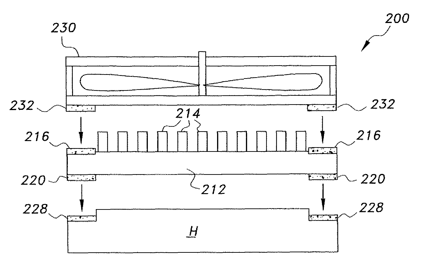
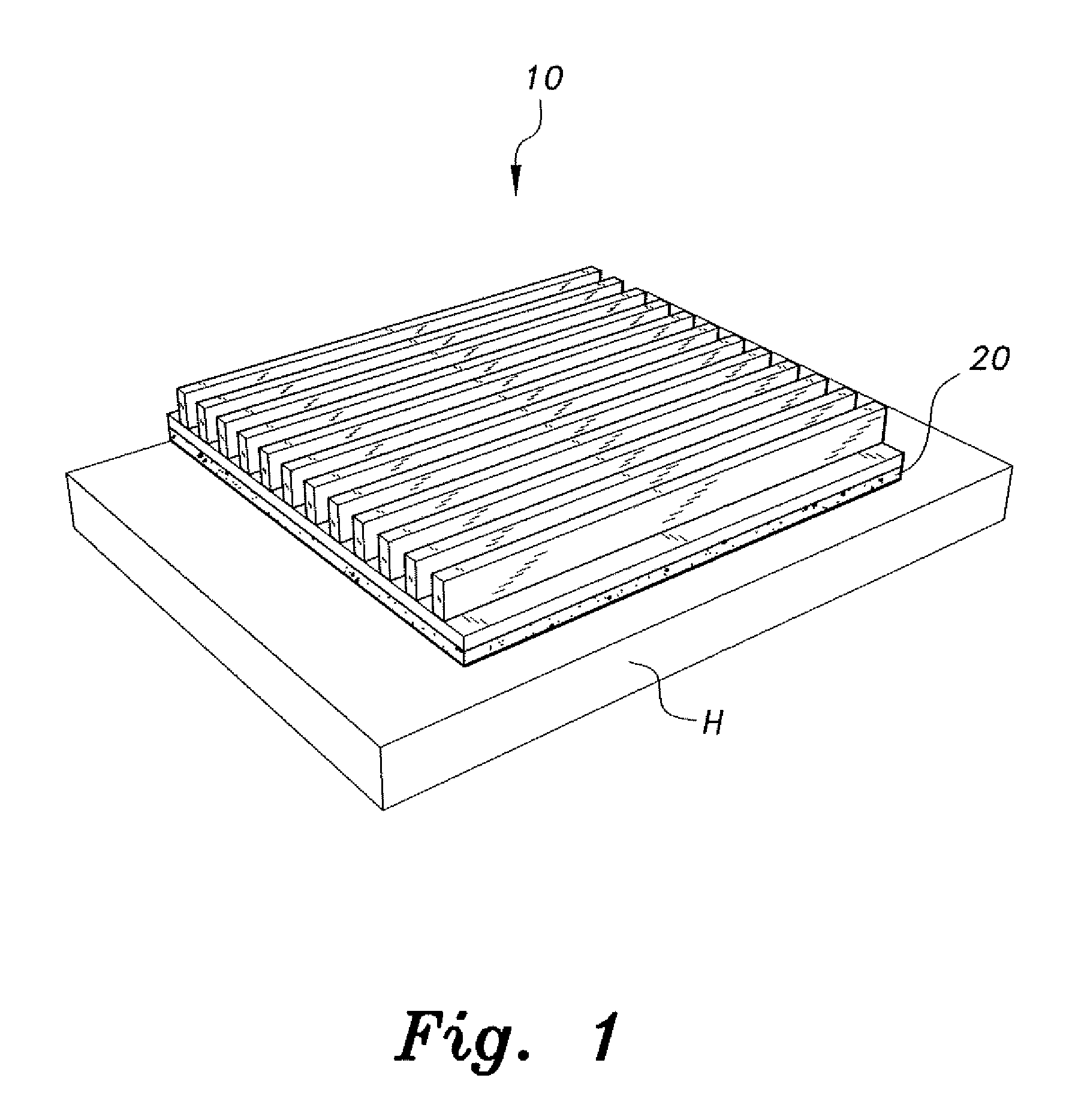
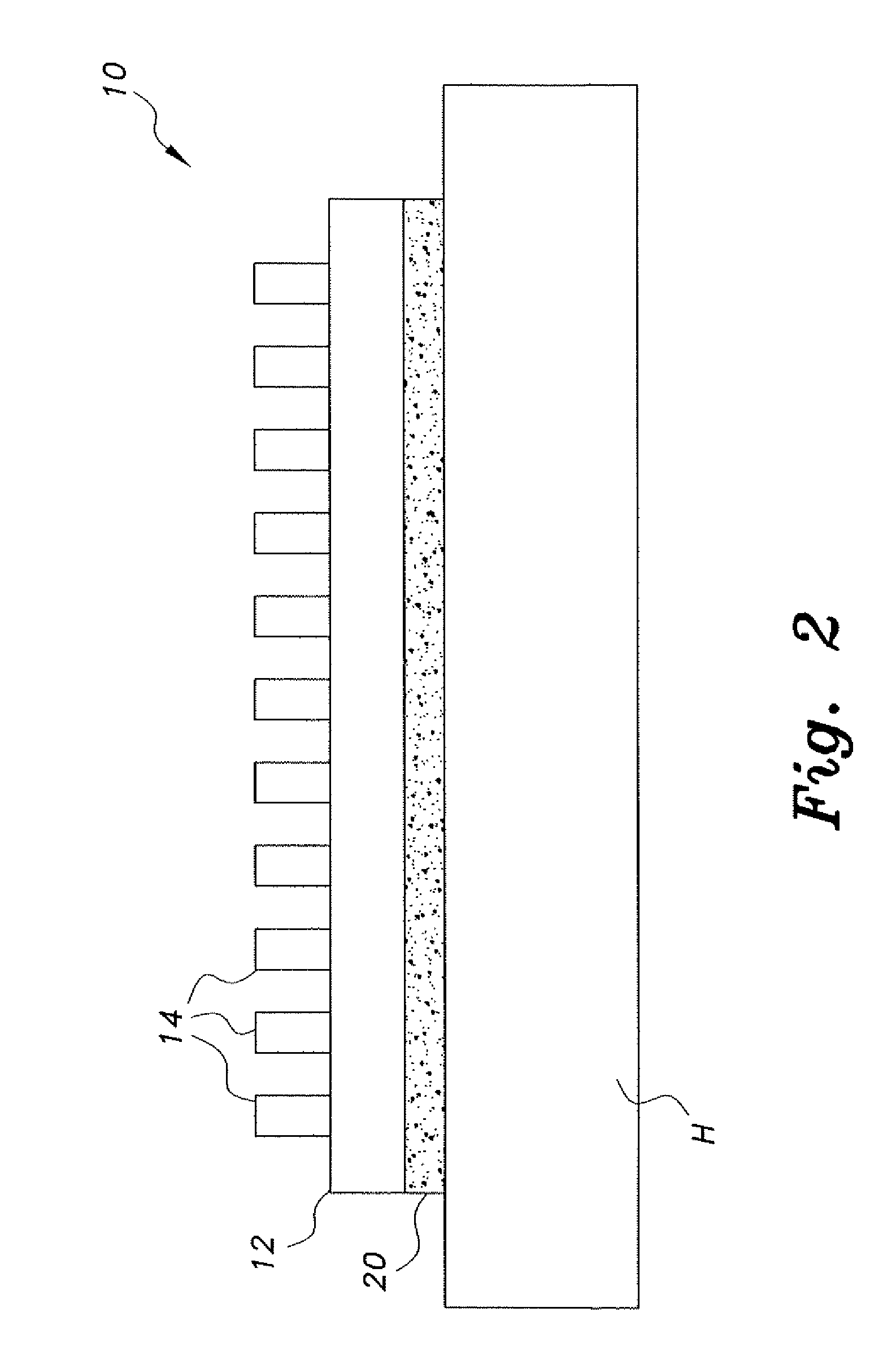
[0019]The add-on heat sink, the first embodiment of which is generally referred to by the reference number 10, provides fast and easy installation of the heat sink in minimal space. As shown in FIGS. 1 and 2, the add-on heat sink 10 includes an elongate base 12 and a plurality of extending fins 14 (for providing greater surface area for the dissipation of heat) attached to the base 12. The base can be a rectangular plate constructed from thermally conductive plastics, metals, composites and / or combinations thereof. The fins 14 are constructed as smaller rectangular plates extending perpendicularly from the top surface of the base 12 and made from similar materials. Although the fins 14 are shown to be rectangular, any shape can be used to construct the fins 14. Additionally, the fins 14 can be arranged in various configurations, such as a fan shape, and may extend at non-perpendicular angles and lengths, so long as the desired heat transfer performance is maintained. The fins 14 pro...


PUM

PropertyMeasurementUnit
thermally conductiveaaaaaaaaaa
heataaaaaaaaaa
pressureaaaaaaaaaa

Abstract

The add-on heat sink includes an elongate base having a plurality of fins extending from a surface thereof. A magnetic layer is disposed on the bottom of the base, which permits the add-on heat sink to be installed on any ferromagnetic heated surface. The magnetic layer is composed of either a polymer matrix having a plurality of thermally conductive structural components and a plurality of magnetic particles dispersed therein, or a thermally conductive polymer having magnetic particles dispersed therein. Alternatively, if the heated surface is not ferromagnetic, the heat sink may be magnetically attached by adhesively attaching mating magnetic and ferromagnetic pads to the heat sink and to the heated surface. This configuration allows the add-on heat sink to be installed with minimal footprint. Optionally, a fan may be magnetically attached to the heat sink to cool the heated surface by both conduction and convection.

Description

BACKGROUND OF THE INVENTION[0001]1. Field of the Invention[0002]The present invention relates to heat transfer devices, and particularly to an add-on heat sink for easy connection to and dissipation of heat from heated structures.[0003]2. Description of the Related Art[0004]Many common electro-mechanical devices used at home, office and elsewhere generate excessive amounts of heat. This can lead to failure, decrease in performance, and / or production of undesirable electromagnetic noise. In some cases, this can lead to a perception of low quality when the device is actually functioning well and as intended.[0005]Traditionally, heat levels in a heated structural element have been reduced in a passive manner by mounting a heat sink on the surface of the structure. Two methods have been commonly applied to facilitate this. One uses a thermally conductive adhesive and the other utilizes mechanical means, such as screws, clips and other types of fasteners.[0006]In the case of the former, ...

Claims


Application Information

Patent Timeline
Patent Type & Authority Patents(United States)
IPC IPC(8): H01L23/40H05K7/20
CPCH01L23/40H05K7/20172F28F2275/22F28F3/02F28F2013/006H01L2924/0002H01L2924/00
Inventor HAWWA, MUHAMMAD A.
Owner KING FAHD UNIVERSITY OF PETROLEUM AND MINERALS
Why Eureka
Try Eureka