Turbine blade cooling system with bifurcated mid-chord cooling chamber

a cooling system and turbine blade technology, applied in the field of turbine blade cooling systems, can solve the problems of thermal stress through the blade, low efficiency of the cooling system, so as to improve the manufacturability, reduce the overall cooling flow requirement, and improve the effect of efficiency

Inactive Publication Date: 2015-02-03
SIEMENS AG
View PDF9 Cites 18 Cited by
  • Summary
  • Abstract
  • Description
  • Claims
  • Application Information

AI Technical Summary

Benefits of technology

[0008]The leading edge supply chamber and the pressure side serpentine cooling channel may be separated by rib, thereby preventing cooling fluid movement between the leading edge supply chamber and the pressure side serpentine cooling channel. The leading edge supply chamber and the suction side serpentine cooling channel may be separated by rib, thereby preventing cooling fluid movement between the leading edge supply chamber and the suction side serpentine cooling channel.
[0010]The cooling system of the turbine blade is advantageous for numerous reasons. In particular, the bifurcated mid-chord cooling chamber increases the efficiency of the turbine blade cooling system in the turbine blade. For instance, the bifurcated mid-chord cooling chamber enables the overall cooling flow requirement to be reduced by enabling the cooling system proximate to the pressure sidewall to be tailored based on heating load. The bifurcated mid-chord cooling chamber also enables high aspect ratio flow channels to be used, which improves the manufacturability, reduces the difficulty of installing film cooling holes, increases the internal hot surface area for turbulators to enhance internal cooling, and increases the internal convective area for the hot gas side area ratio. The bifurcated mid-chord cooling chamber also eliminates design issues, such as back flow margin (BFM) and high blowing ratio, that are typical for suction side film cooling holes in conventional designs. The bifurcated mid-chord cooling chamber may also utilize a single cooling flow circuit, which increases the cooling flow mass flux, thereby yielding a higher internal convective cooling performance than a conventional mid-chord serpentine cooling channel.

Problems solved by technology

In addition, turbine blades often contain cooling systems for prolonging the life of the blades and reducing the likelihood of failure as a result of excessive temperatures.
However, centrifugal forces and air flow at boundary layers often prevent some areas of the turbine blade from being adequately cooled, which results in the formation of localized hot spots.
In addition, the hot gases increase the temperature of the blade, causing the development of thermal stresses through the blade.

Method used


Image

  • Turbine blade cooling system with bifurcated mid-chord cooling chamber
  • Turbine blade cooling system with bifurcated mid-chord cooling chamber
  • Turbine blade cooling system with bifurcated mid-chord cooling chamber

Examples


Embodiment Construction

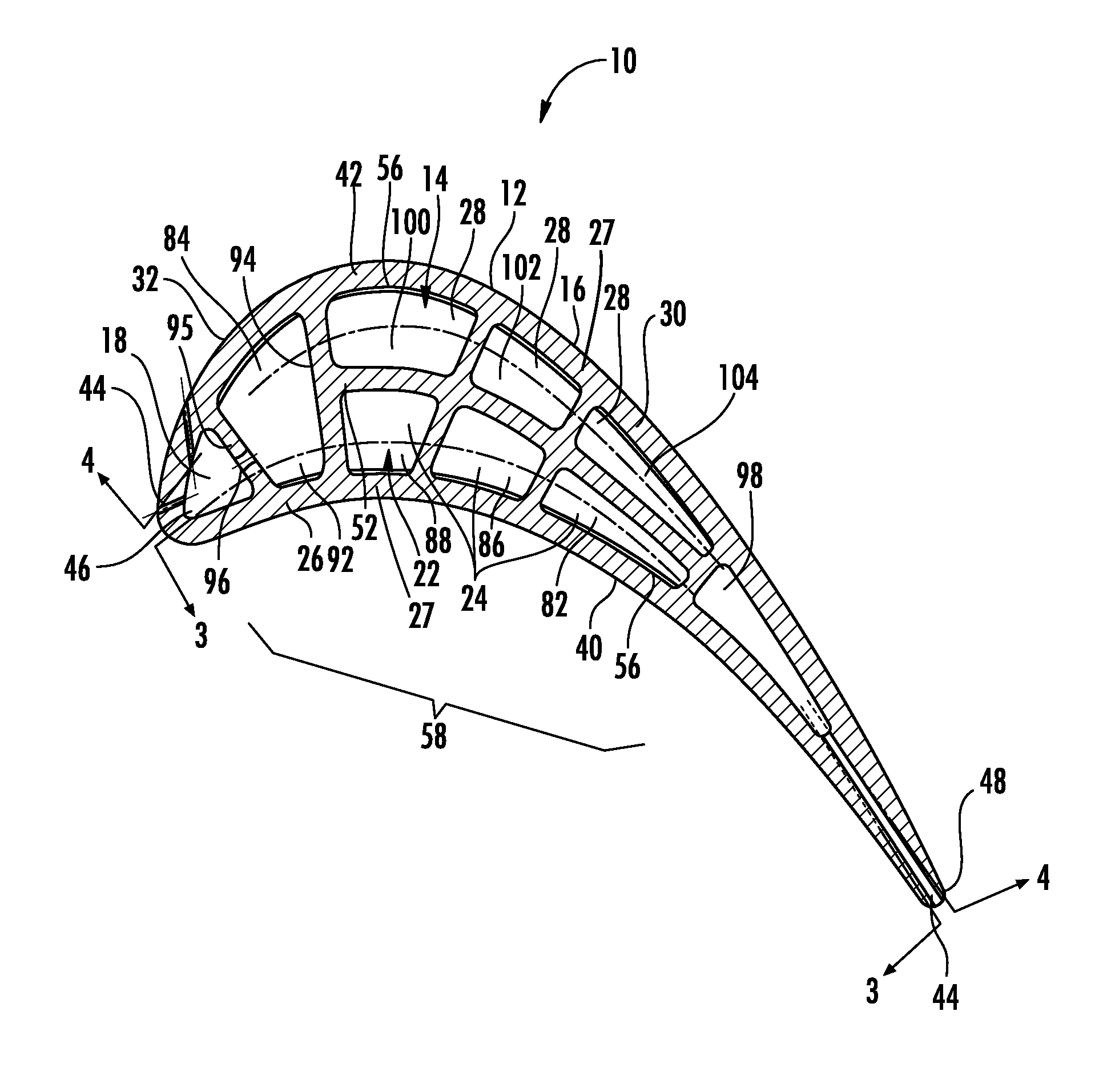
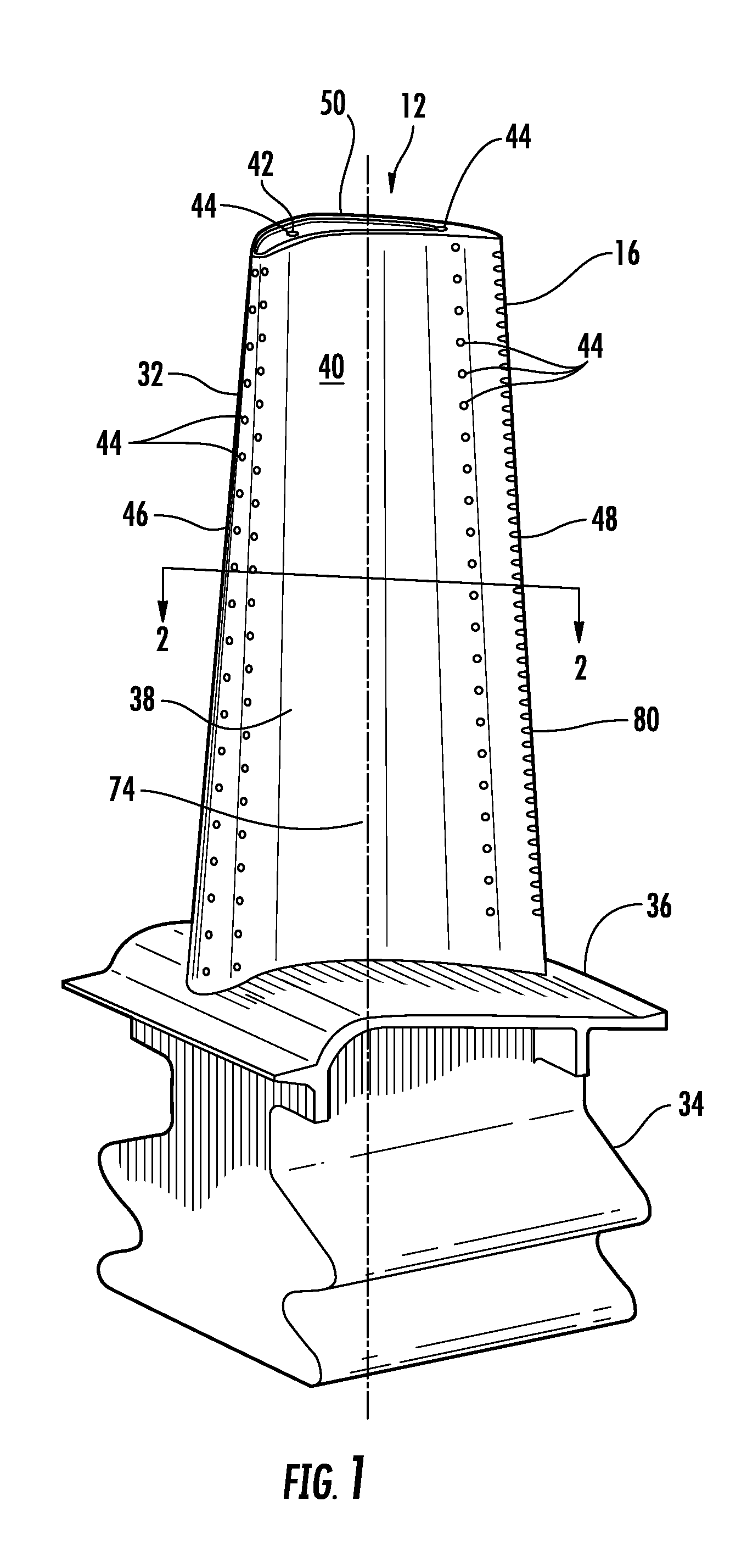
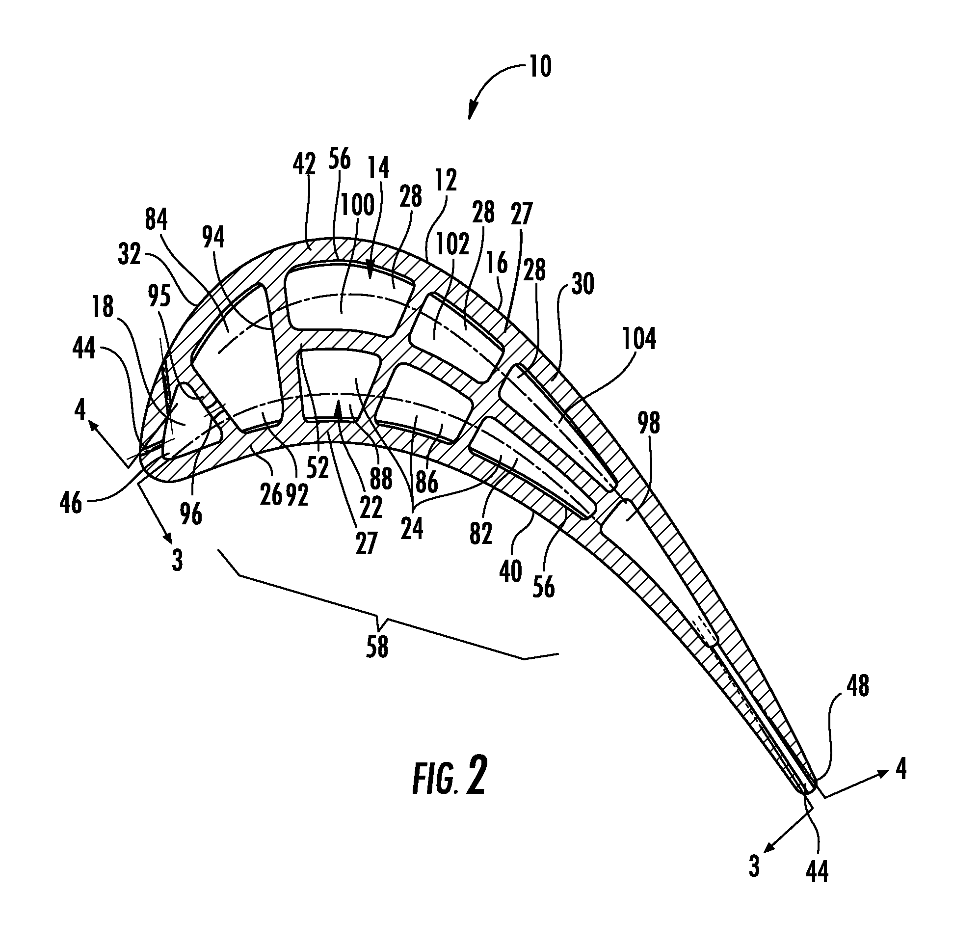
[0017]As shown in FIGS. 1-4, this invention is directed to a turbine blade cooling system 10 for turbine blades 12 used in turbine engines. The turbine blade 12 may include a bifurcated mid-chord cooling chamber 22 formed from a pressure side serpentine cooling channel 24 and a suction side serpentine cooling channel 28 with cooling fluids passing through the pressure side serpentine cooling channel 28 in a direction from a trailing edge 48 toward a leading edge 46 and in an opposite direction through the suction side serpentine cooling channel 28. The pressure side and suction side serpentine cooling channels 24, 28 may flow counter to each other, thereby yielding a more uniform temperature distribution than conventional serpentine cooling channels.

[0018]The turbine blade cooling system 10 may be directed to a cooling system 10 located in a cavity 14, as shown in FIG. 2, positioned between two or more walls 27 forming a housing 16 of the turbine blade 12. The cooling system 10 may ...


PUM


Abstract

A cooling system for a turbine blade of a turbine engine having a bifurcated mid-chord cooling chamber for reducing the temperature of the blade. The bifurcated mid-chord cooling chamber may be formed from a pressure side serpentine cooling channel and a suction side serpentine cooling channel with cooling fluids passing through the pressure side serpentine cooling channel in a direction from the trailing edge toward the leading edge and in an opposite direction through the suction side serpentine cooling channel. The pressure side and suction side serpentine cooling channels may flow counter to each other, thereby yielding a more uniform temperature distribution than conventional serpentine cooling channels.

Description

FIELD OF THE INVENTION[0001]This invention is directed generally to turbine blades, and more particularly to cooling systems in hollow turbine blades.BACKGROUND[0002]Typically, gas turbine engines include a compressor for compressing air, a combustor for mixing the compressed air with fuel and igniting the mixture, and a turbine blade assembly for producing power. Combustors often operate at high temperatures that may exceed 2,500 degrees Fahrenheit. Typical turbine combustor configurations expose turbine blade assemblies to these high temperatures. As a result, turbine blades must be made of materials capable of withstanding such high temperatures. In addition, turbine blades often contain cooling systems for prolonging the life of the blades and reducing the likelihood of failure as a result of excessive temperatures.[0003]Typically, turbine blades are formed from a root portion at one end and an elongated portion forming a blade that extends outwardly from a platform coupled to t...

Claims


Application Information

Patent Timeline
Patent Type & Authority Patents(United States)
IPC IPC(8): F01D5/18F01D5/08
CPCF01D5/087F01D5/187F05D2250/185F05D2260/202F05D2260/2212
Inventor LEE, CHING-PANG
Owner SIEMENS AG
Why Eureka
Try Eureka