
Antenna device and magnetic resonance imaging device

a magnetic resonance imaging and antenna technology, applied in the field of antenna devices and magnetic resonance imaging devices, can solve the problems of increasing production costs and maintenance costs at the time of quality control, antennas are significantly changed, and cylindrical conductors do not serve as perfect rf shields, so as to achieve the effect of reducing production and maintenance costs

Active Publication Date: 2015-02-03
FUJIFILM HEALTHCARE CORP
View PDF19 Cites 7 Cited by
  • Summary
  • Abstract
  • Description
  • Claims
  • Application Information

AI Technical Summary

Benefits of technology

The patent text describes a new invention that eliminates limitations on the size of the RF coil in MRI devices, which can lower production and maintenance costs.

Problems solved by technology

As the number of capacitors increases, production cost and cost for quality control at the time of maintenance thereof increase.
However, in this volume antenna, the two cylindrical conductors carry out the same function as that of the ring portions of the birdcage type antenna, and therefore the cylindrical conductors do not serve as a perfect RF shield.
Accordingly, when a conductor or a subject approaches from outside of the antenna, the sensitivity of the antenna significantly changes, and thus it is not suitable for practical use.
Moreover, in this volume antenna, thickness of the dielectric material is a large factor for determining the resonance frequency, and therefore adjustment of the frequency is also difficult.

Method used


Image

  • Antenna device and magnetic resonance imaging device
  • Antenna device and magnetic resonance imaging device
  • Antenna device and magnetic resonance imaging device

Examples


example

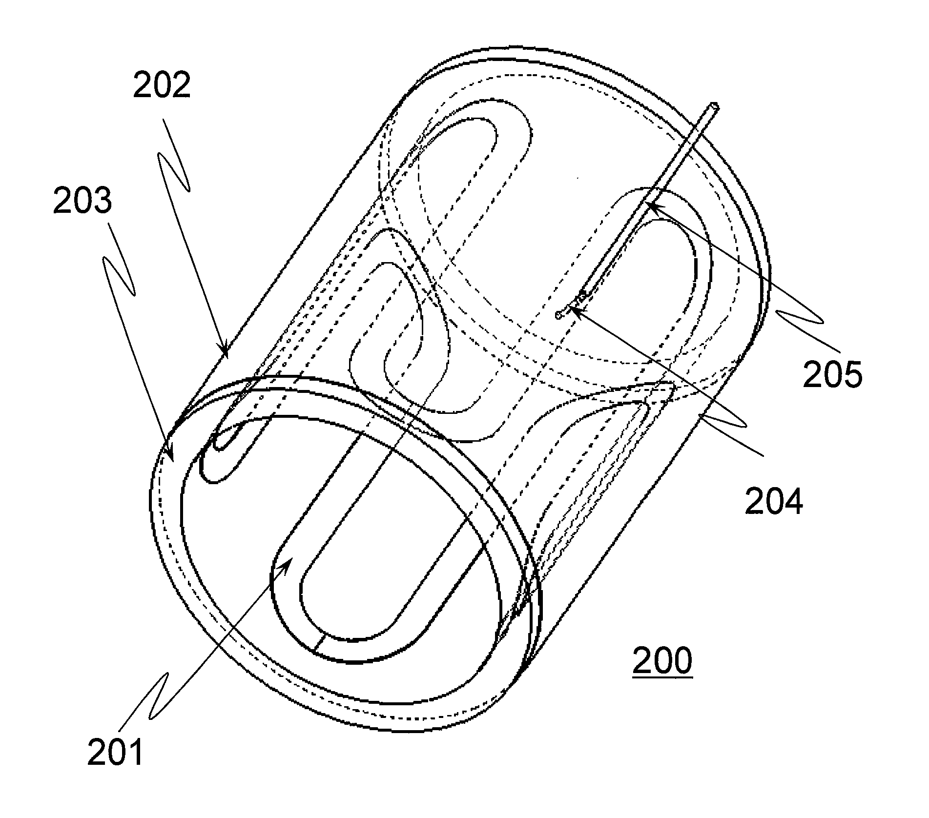
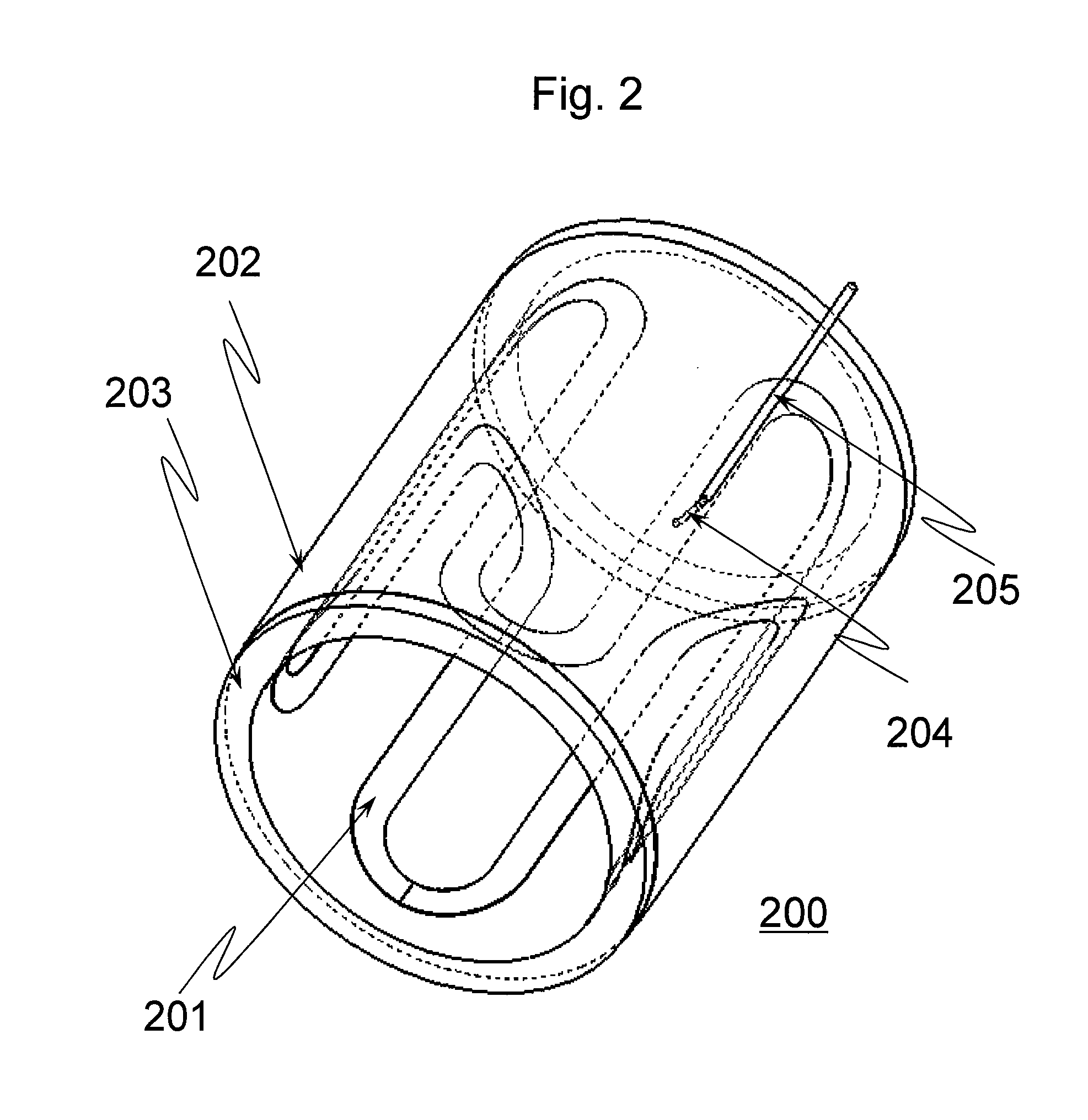
[0089]There will be explained an example of the volume antenna 200 according to the embodiment explained above for the case of using it as a volume antenna for the head of an MRI device used at a magnetic field intensity of 3 teslas (henceforth referred to as MRI device of 3 teslas). The imaging nuclide was hydrogen nucleus. The housing 203 was formed with a transparent acrylic resin showing a relative permittivity ∈r of about 2.6 in such a size that the human head could be entered in it. Specifically, the internal diameter was 280 mm, the external diameter was 320 mm, and the length was 270 mm.

[0090]On the external side surface of the cylinder of the housing 203, a copper foil (copper sheet) having a thickness of 35 μm was adhered as the cylindrical conductor 202. Two of the copper foils having a length of 270 mm in the direction of the axis of the cylinder and a developed length of 600 mm for the circumferential direction were piled up and adhered on the housing 203 with a double-...


PUM


Abstract

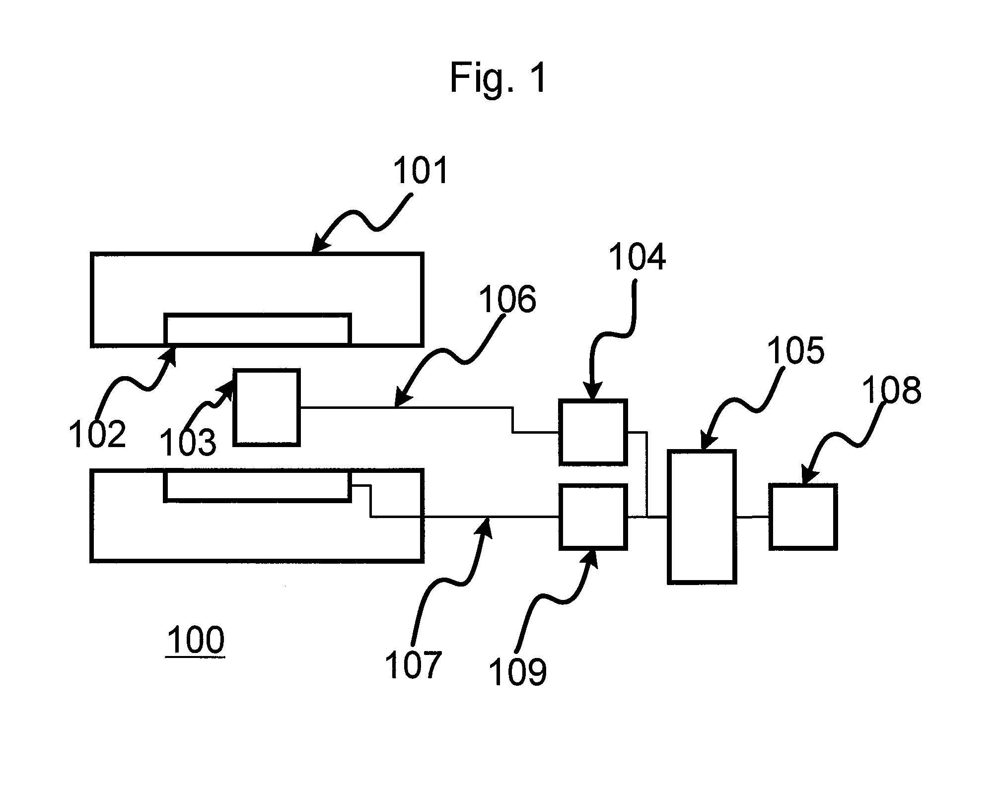
Manufacture cost and maintenance cost of RF coils of MRI devices are reduced without any limitation concerning size of the coils. By constituting an antenna device for magnetic resonance imaging devices with a cylindrical outer conductor, a looped ribbon-shaped conductor disposed inside the cylindrical outer conductor along the cylindrical surface, and a feed point for transmission and / or reception between the cylindrical conductor and the ribbon-shaped conductor, and disposing the ribbon-shaped conductor so that length thereof can be readily adjusted, there is provided an antenna device for magnetic resonance imaging devices that generates a magnetic field component perpendicular to the central axis of the cylinder at a desired resonance frequency and shows sensitivity without using capacitors and without being imposed any limitation concerning size in the diametral direction of the cylinder.

Description

TECHNICAL FIELD[0001]The present invention relates to an antenna device for transmitting and receiving electromagnetic waves, and a magnetic resonance imaging device (henceforth referred to as MRI device) using the same.BACKGROUND ART[0002]MRI devices irradiate electromagnetic waves on a subject placed in a uniform static magnetic field generated by a magnet to excite nuclear spins in the subject and receive magnetic resonance signals as electromagnetic waves generated by the nuclear spins for imaging the subject. The irradiation of the electromagnetic waves and the reception of the magnetic resonance signals are attained by a device called RF antenna or RF coil, which transmits or receives radio frequency (RF) electromagnetic waves.[0003]RF coils or antennas are roughly classified into two groups, those called surface antennas or local antennas and those called volume coils or volume antennas. Surface antennas have a round shape or planar shape, and show sensitivity in neighborhood...

Claims


Application Information

Patent Timeline
Patent Type & Authority Patents(United States)
IPC IPC(8): G01R33/44H01Q9/04A61B5/055G01R33/34G01R33/341
CPCG01R33/34046G01R33/34053G01R33/34061G01R33/341A61B5/055G01R33/34007
Inventor HABARA, HIDETABITO, YOSHITAKAOCHI, HISAAKISOUTOME, YOSHIHISAKANEKO, YUKIODOHATA, MASAYOSHI
Owner FUJIFILM HEALTHCARE CORP
Learn More