Tap changer and vacuum interrupter for such a tap changer

a vacuum interrupter and tap changer technology, applied in the field of tap changers, can solve the problems of transient tap short-circuit, regulated can also arise, and unpredictable switching surge voltage, and achieve the effect of reducing complexity and the required individual components, and high surge voltage strength

Inactive Publication Date: 2015-02-03
SIEMENS AG
View PDF11 Cites 5 Cited by
  • Summary
  • Abstract
  • Description
  • Claims
  • Application Information

AI Technical Summary

Benefits of technology

[0011]In other words: present in the known tap changer in each main current branch and auxiliary current branch is thus a mechanical changeover switch that is connected in series with the respective vacuum-switching tube and that ensures a complete electrical isolation of the respective winding tap, which is not connected, and thus a high surge voltage strength.
[0013]It is therefore the object of the present invention to indicate a tap changer for uninterrupted changeover between winding taps of a tapped transformer that enables a reduction in the complexity and in the required individual components, in that case, in particular, makes mechanical switching means redundant and, in addition, has a high surge voltage strength. Moreover, it is an object of the present invention to indicate a vacuum-switching tube that is usable particularly advantageously for such a developed tap changer.SUMMARY OF THE INVENTION
[0015]The dielectric strength of the novel vacuum-switching tube is increased in that the individual vacuum switching paths of the several contact systems are arranged in separate, i.e. mutually sealed, vacuum switching chambers, but in a common housing. In other words: The risk of differences in potential existing between the different contact systems, which could lead to an overlapping arc, are solved in accordance with the invention by the fact that several separate vacuum switching chambers are provided in which the contact systems are arranged to be respectively electrically separated from one another.

Problems solved by technology

Such undesired surge voltages, the level of which is substantially attributable to the construction of the tapped transformer and of the winding parts between the individual taps, are on the one hand lightning surge voltages resulting from lightning strikes in the mains.
On the other hand, switching surge voltages caused by unpredictable switching surges in the mains to be regulated can also arise.
In a case of an inadequate surge voltage strength of the tapped transformer on the one hand a transient tap short-circuit can arise if the vacuum-switching tube in the load branch not conducting the load current breaks down.
Not only the small constructional space currently available in modern apparatus, but also economics as well as serviceability of such vacuum-switching tubes make such over-dimensioning appear disadvantageous.
All tap changers known from the prior art require a plurality of vacuum-switching tubes and additional mechanical switching means per phase, which due to the high demand for space by the individual switching means and the accompanying constructional and mechanical outlay is disadvantageous and, above all, costly.

Method used


Image

  • Tap changer and vacuum interrupter for such a tap changer
  • Tap changer and vacuum interrupter for such a tap changer
  • Tap changer and vacuum interrupter for such a tap changer

Examples


Embodiment Construction

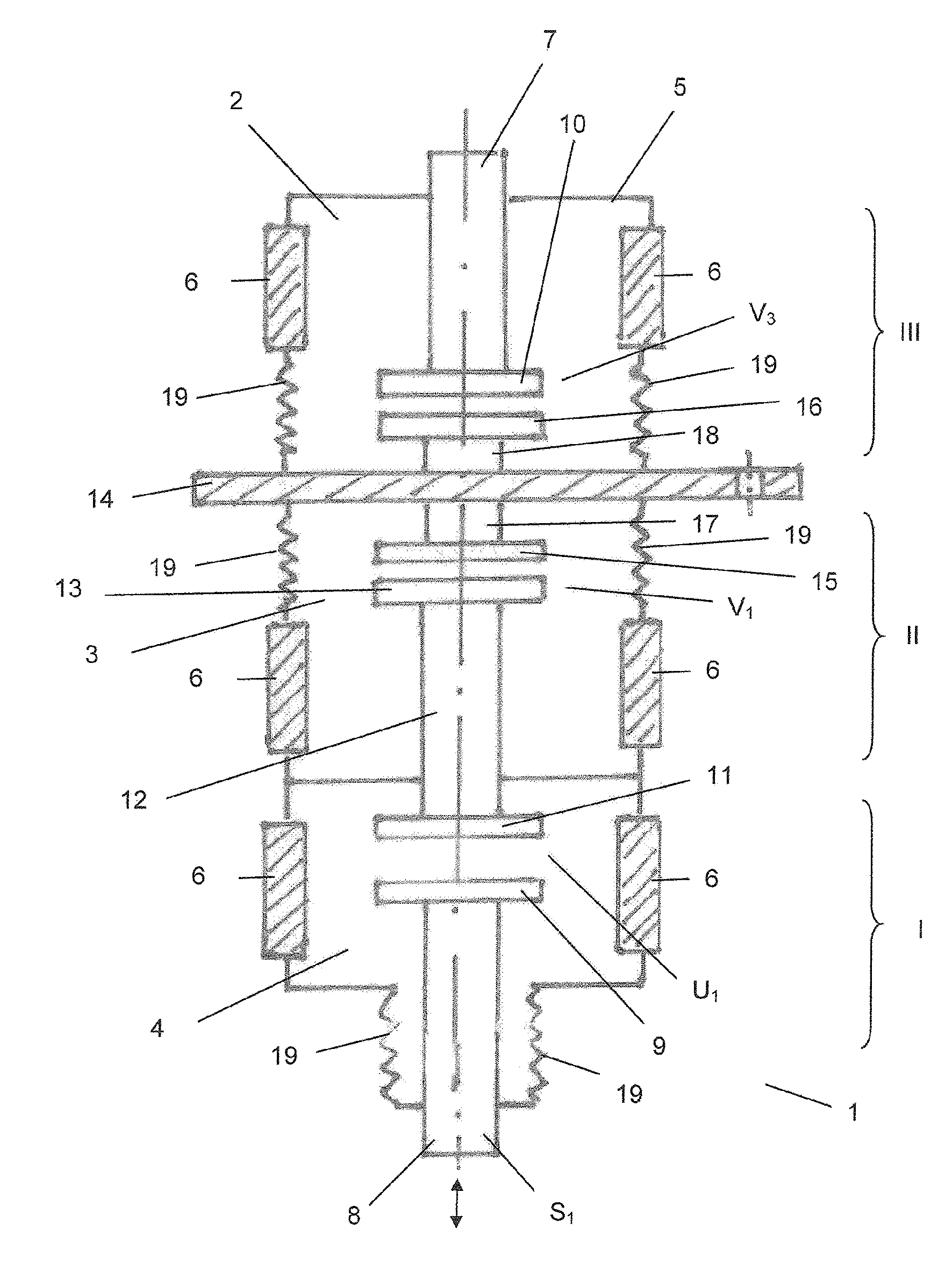
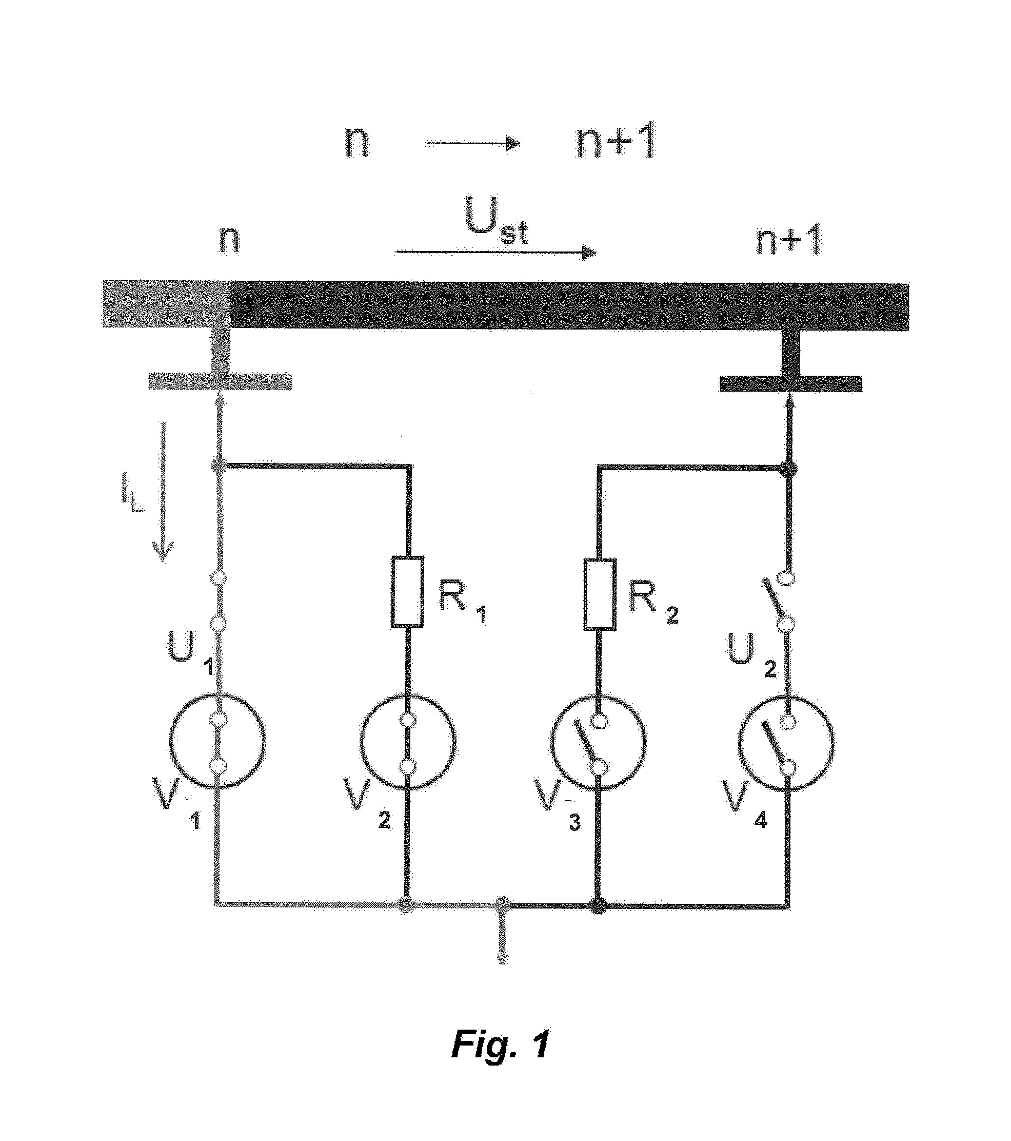
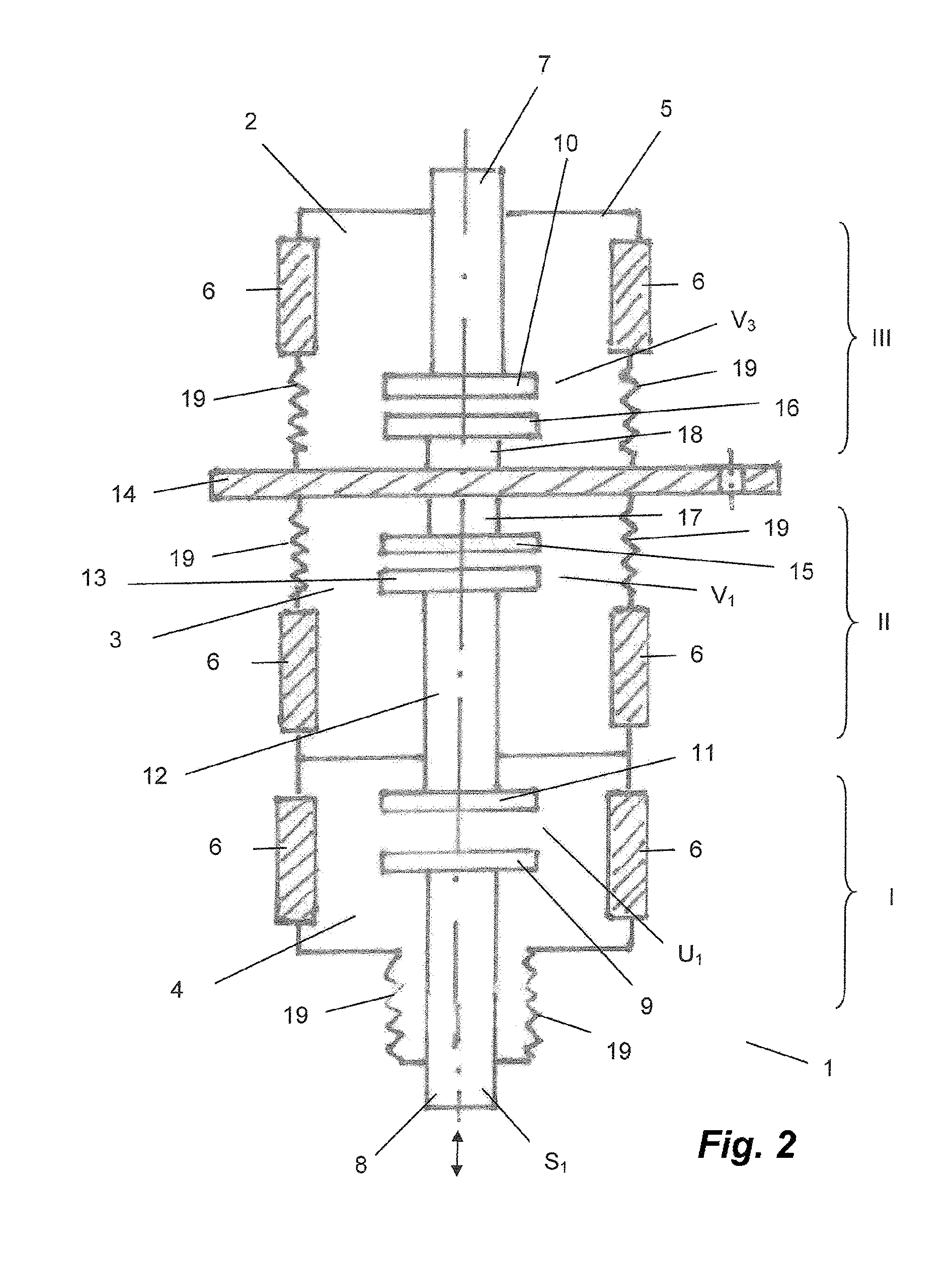
[0024]A tap changer known from the prior art is shown in FIG. 1. It comprises a first load branch in which a vacuum-switching tube V1 acting as a main contact and a mechanical changeover switch U1 connected in series therewith, as well as in parallel therewith a switchover resistor R1 and a vacuum-switching tube V2 acting as a resistance contact, are disposed. The second load branch has, entirely analogously, a vacuum-switching tube V4 and a mechanical changeover switch U2 connected in series therewith as well as in parallel therewith a further switchover resistor R2 and a vacuum-switching tube V3 acting as a resistance contact. The known tap changer thus has two vacuum-switching tubes per load branch, thus four vacuum-switching tubes per phase. The starting position, in which the tap n is connected, corresponds with the setting, which is illustrated in FIG. 1, of the individual switching elements. The changeover is carried out in the following steps:[0025]vacuum-switching tube V1 [...


PUM

PropertyMeasurementUnit
electrically conductiveaaaaaaaaaa
resistanceaaaaaaaaaa
surge voltage strengthaaaaaaaaaa

Abstract

The invention relates to a tap changer for the interruption-free switchover between winding taps of a tap-changing transformer. Furthermore, the present invention relates to a novel vacuum interrupter which is particularly suitable for such a tap changer. The tap changer according to the invention is based on the general concept of combining in each case one main contact (V1) and one mechanical switching means (U1), connected in series therewith, of a first load branch and an additional resistive contact (V3) of a second load branch in only a single vacuum interrupter (1) with a common housing (5). The vacuum interrupter (1) according to the invention is furthermore based on the general inventive concept of replacing the functionalities of two required vacuum interrupters in accordance with the prior art and an additional mechanical switching means with a single vacuum interrupter (1) according to the invention by virtue of combining the design of a vacuum interrupter (1) with a plurality of moveable contact systems (I, II, III), which are arranged in separate vacuum interrupter chambers (2, 3, 4) which are sealed with respect to one another.

Description

CROSS REFERENCE TO RELATED APPLICATIONS[0001]This application is the US-national stage of PCT application PCT / EP2012 / 053587 filed 2 Mar. 2012 and claiming the priority of German patent application 102011015922.3 itself filed 2 Apr. 2011.[0002]The invention relates to a tap changer for uninterrupted changeover between winding taps of a tapped transformer.[0003]The present invention additionally relates to a novel vacuum-switching tube particularly suitable for such a tap changer.[0004]A tap chamber having in total four vacuum-switching tubes per phase is known from DE 20 21 575. Provided in each of the two load branches are a respective vacuum-switching tube as main contact and a respective further vacuum-switching tube, in series connection with a switchover resistor, as resistance contact.[0005]In the case of an uninterrupted load changeover from the previous winding tap n to a new, preselected winding tap n+1 initially the main contact of the side to be switched off is opened and ...

Claims


Application Information

Patent Timeline
Patent Type & Authority Patents(United States)
IPC IPC(8): H01H21/12H01H33/66G05F1/14H01F29/04H01H9/00H01H33/16H01H33/664H01H33/666
CPCH01F29/04H01H9/0038H01H33/6647H01H33/16H01H2033/6668H01H9/00H01H33/664
Inventor HAMMER, CHRISTIANALBRECHT, WOLFGANGPIRCHER, CHRISTIANREHKOPF, SEBASTIANSACHSENHAUSER, ANDREASRAEDLINGER, KONRADSTELZER, ANDREASTEICHMANN, JOERGLAWALL, ANDREASRENZ, ROMANKOSSE, SYLVIOHARTMANN, WERNERWENZEL, NORBERT
Owner SIEMENS AG
Why Eureka
Try Eureka