
Method for determining the path length of a sample and validating the measurement obtained

a path length and optical path technology, applied in the direction of measurement devices, material analysis through optical means, instruments, etc., can solve the problems of not being able to provide fully traceability, unable to work with the very small volume of sample required in biotechnology and pharmaceutical research, and only comparative measurements

Active Publication Date: 2015-02-03
STARNA SCI
View PDF11 Cites 2 Cited by
  • Summary
  • Abstract
  • Description
  • Claims
  • Application Information

AI Technical Summary

Benefits of technology

The invention is a device that can accurately measure the absorption of small samples of liquid. It does this by dropping the sample onto an optical measuring device and ensuring that it is the same volume as specified. This method is much more accurate than previous methods and can provide results that can be easily traced to international standards. The device is also cleaner and less prone to contamination and background noise. In addition, it is much faster than previous methods. The technical effects of this invention include improved accuracy, ease of tracking to standards, and improved speed.

Problems solved by technology

Further, the same problem may arise for very small volumes of sample in a horizontal system.
Although the methods and apparatus described in these documents are an improvement over other previous systems, the measurements are only comparative and are not suitable for working with the very small volumes required in biotechnology and pharmaceutical research.
However, it does not provide fully traceable results because each measurement cannot be validated to an accurate standard.
Thus, the path length measurement obtained cannot be used as part of ISO-compliant protocols nor can it be used to obtain ISO-compliant results.

Method used


Image

  • Method for determining the path length of a sample and validating the measurement obtained
  • Method for determining the path length of a sample and validating the measurement obtained
  • Method for determining the path length of a sample and validating the measurement obtained

Examples


Embodiment Construction

[0021]According to the present invention there is provided a method for traceably determining an unknown optical path length of a sample in an optical measuring device, which optical measuring device is validated using a certified reference material having a specified nominal absorbance, the sample being dissolved or suspended in a solvent, which solvent is also the solvent of the certified reference material,[0022]wherein the certified reference material is contained in first and second closed cuvettes, which cuvettes have a first and second specified path length and a specified accuracy;[0023]wherein absorbance of the certified reference material is measured to obtain a first absorbance measurement for the first specified path length; absorbance of the certified reference material is then measured for a second path length to obtain a second absorbance measurement;[0024]wherein a dropping device drops a specified volume of the solvent on the optical measuring device so that the pat...


PUM

PropertyMeasurementUnit
wavelengthsaaaaaaaaaa

Abstract

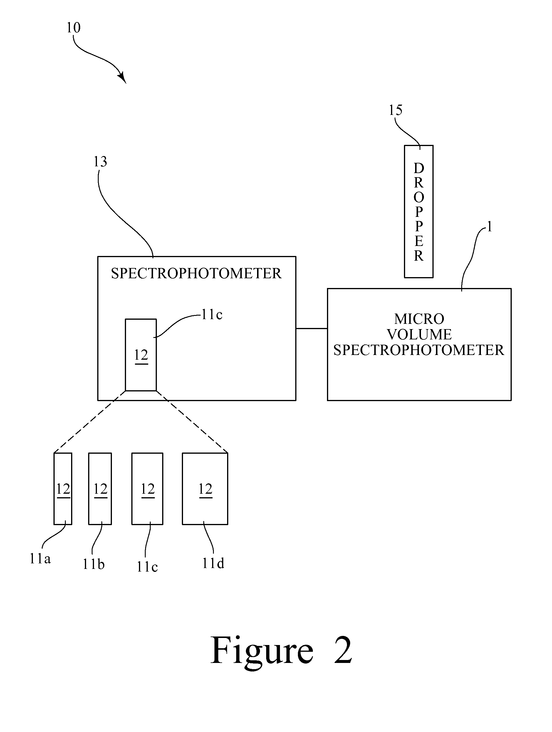
A for traceably determining an unknown optical path length of a sample in an optical measuring device comprises the steps of: providing a drop analyzer connected to a standard spectrophotometer; providing a certified reference material contained in first and second closed high accuracy cuvettes; measuring absorbance of the certified reference material to obtain a first absorbance measurement for the first specified path length; measuring absorbance of the certified reference material for a second path length to obtain a second absorbance measurement; using a dropping device to drop a specified volume of the solvent on an optical surface so that the path length of the specified volume can be determined by reference to the first and second absorbance measurement; and using the dropping device to drop the same volume of sample as the specified volume of solvent on the optical measuring device.

Description

CROSS-REFERENCE TO RELATED APPLICATIONS[0001]The present application claims priority to GB Application No. 1116080.1 filed on Sep. 16, 2011.BACKGROUND OF THE INVENTION[0002]The present invention relates to a method for determining an unknown optical path length and for validating the measurement obtained, in particular a traceable method for determining the path length of a volume such as a drop.[0003]Metrology is a science which is concerned with measurement; specifically, it includes experimental and theoretical determinations in any field of technology. The international vocabulary of metrology is maintained by the International Organisation for Standardisation (ISO) and is currently in its third revision.[0004]One of the core bases of metrology is metrological traceability, which is defined as the property of the result of a measurement or the value of a standard whereby it can be related to references, usually national or international standards, through an unbroken chain of co...

Claims


Application Information

Patent Timeline
Patent Type & Authority Patents(United States)
IPC IPC(8): G01N21/00G01N21/11G01N21/27
CPCG01N21/11G01N21/274G01N21/278G01N2201/0662G01N2201/1286G01N21/03G01N21/31
Inventor HULME, A KEITHHAMMOND, JOHNHULME, NATHAN
Owner STARNA SCI
Learn More