Hand-held hot air device with a digital operating device with a universal operating element

a technology of digital operating device and universal operating element, which is applied in the direction of air heaters, lighting and heating apparatus, apparel, etc., can solve the problems of not being able to operate and adjust independently of fans and heating cartridges, and the actual temperature of air flow cannot be determined, so as to achieve the effect of reducing the energy consumption of heating elements, avoiding overheating of heating elements, and consuming large amounts of energy

Active Publication Date: 2015-02-03
LEISTER TECHNOLOGIES
View PDF24 Cites 16 Cited by
  • Summary
  • Abstract
  • Description
  • Claims
  • Application Information

AI Technical Summary

Benefits of technology

[0012]Regarding a simple operation of the hand-held hot air device according to the invention, it proved to be favorable if the universal operating element was designed as self-returning, at least in the axial direction. In the rotary direction, the universal operating element may be designed as self-returning or non-self-returning. This depends on whether the universal operating element is designed in this direction as a bit generator or as a switch. In this manner, all operating parameters or operating conditions of the hand-held hot air device can be adjusted in a simple way. In conjunction with the visualization by means of the display, even complex adjustment and setting processes can be shown and performed in a way that is simple to understand.
[0014]In a favored embodiment of the invention, the microprocessor control system comprises a software locking function for the operating device so that the microprocessor control system does not react to an accidental actuation of the universal operating element. This prevents the adjustment parameters for the air volume and the air temperature of the hot air flow as well as the operating conditions of the hand-held hot air device from being accidentally changed in an undesirable manner during the use of the hand-held hot air device according to the invention. In order to override the software locking function, the operating element must be pushed and / or rotated in a certain way that generates a given command code.
[0017]Frequently, users use hand-held hot air devices for the same process. For this, they are adjusted optimally just once and thereafter only switched on and off by means of the universal operating element. When they are switched on, the last process parameters that were used are called up again. Many end users use automatic hot air devices for the essential part of a task, and employ the hand-held hot air device only sporadically for a short period in order to manually work on the areas that cannot be reached by the automatic hot air device. It may take several minutes before a hot air device reaches operating temperature after being switched on. This is why such hand-held hot air devices are frequently switched on when work begins and remain in operation until work ends. While the automatic welding device is in operation and / or the user performs other tasks, known hand-held hot air devices consume large amounts of energy during waiting periods, which is undesirable. In conjunction with semiconductor power switches arranged upstream of the heating element or the fan, the microprocessor control system offers the possibility of a controlled change of the air volume conveyed by the fan and / or of the operating temperature of the heating element for generating the hot air flow. As soon as the desired operating temperature is reached and if the air volume is then readjusted, the process temperature is changed only slightly during the adjustment due to the thermal capacity of the heating element. Meanwhile, the energy consumption of the heating element can also be lowered because the heating element needs to heat only the reduced air volume.
[0018]If the hand-held hot air device is no longer needed, overheating of the heating element can be avoided by means of the cooling-down function while it is taken out of operation. With the cooling-down function activated, the heating element is switched off under microprocessor control while the fan keeps running for a while, thereby cooling it. The run-on period of the fan can be preset, i.e. stored in the microprocessor, or may be controlled by sensor. The activated cooling-down function is signaled to the user via the electronic display. At the end of the run-on period, the new hand-held hot air device shuts down completely and automatically and also blocks via software the input of commands via the universal operating element.
[0020]In a preferred embodiment of the invention, the microprocessor control system comprises a start-up locking function that can be influenced via the universal operating element. The start-up locking function prevents the automatic start-up of the hand-held hot air device when operating voltage is applied to it. Due to the use of semiconductor power switches for controlling the power of the fan and of the heating element, the microprocessor of the hand-held hot air device is capable of switching these on or off in a defined way. When the device is connected to the operating voltage, or when the operating voltage becomes available again after a power failure, the air flow is only generated and heated after the user has deactivated the lock by means of a deliberate input on the universal operating element. This is a safety-related advantage for preventing fires after power outages, in contrast to devices equipped with a main switch.

Problems solved by technology

With the hand-held hot air device known from prior art, it is considered to be a disadvantage that the target temperature of the air flow can only be set approximately, and that the actual temperature of the air flow is not detectable.
It is another disadvantage that the control system acts only on the heating cartridge, and that the fan and the heating cartridge can not be operated and adjusted independently of each other.

Method used


Image

  • Hand-held hot air device with a digital operating device with a universal operating element
  • Hand-held hot air device with a digital operating device with a universal operating element
  • Hand-held hot air device with a digital operating device with a universal operating element

Examples


Embodiment Construction

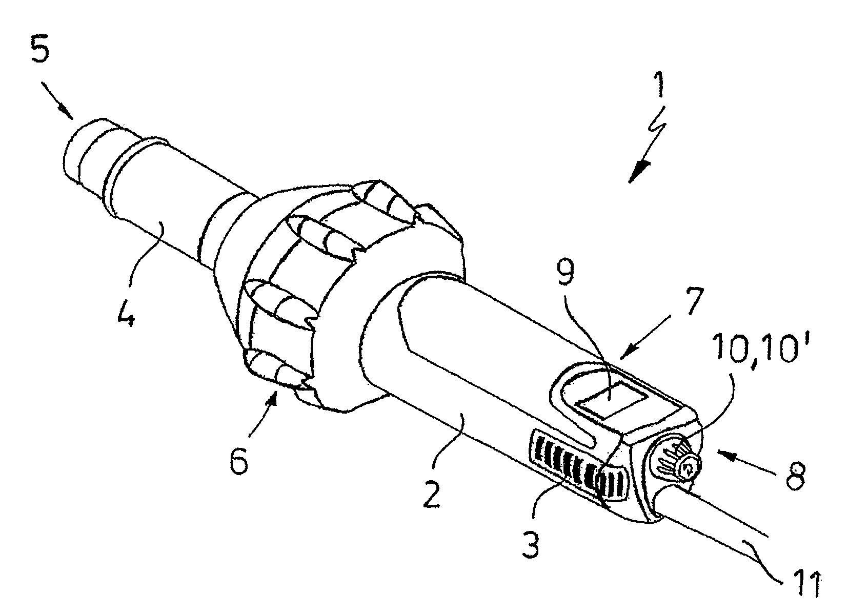
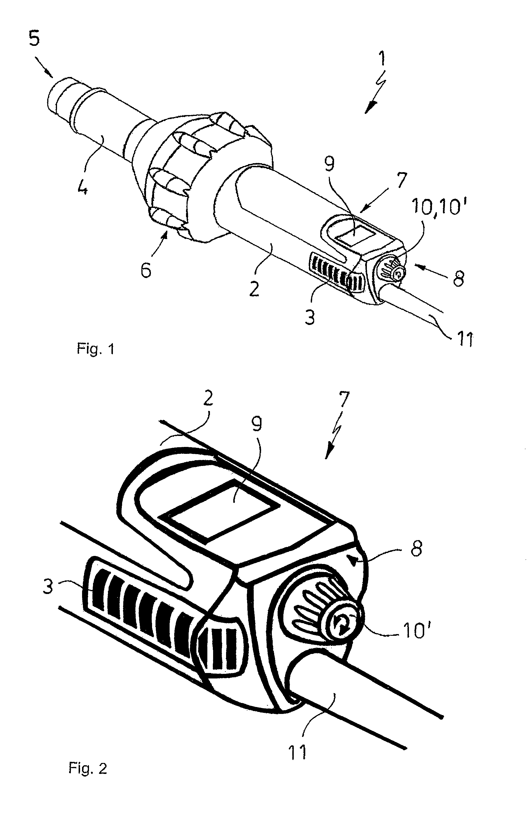
[0026]FIG. 1 shows the embodiment of the invention as an overview drawing, FIG. 2 shows the rear end of the embodiment shown in FIG. 1 in an enlarged detail view. The hand-held hot air device according to the invention 1 comprises a wand-shaped handle part 2 with air inlet openings 3 that is implemented as a plastic housing (2′). The air inlet openings 3 are arranged at the rear of the handle part 2. At the front end of the handle part 2, a metallic air guidance tube 4 protrudes that comprises an air outlet opening 5 at its end facing away from the handle part 2, with an air canal (not shown in the Figures) extending inside the housing (2′) and the air guidance tube 4 from the air inlet openings 3 to the air outlet opening 5. At the transition to the air guidance tube 4, the cylindrical handle part 2 comprises an equally cylindrical front housing section 6 the diameter of which, however, is significantly larger than the rear housing section 7 of the handle part 2. Inside the handle ...


PUM


Abstract

The hand-held hot air device, preferably for the local heating of thermoplastic materials, with a housing that forms a wand-shaped handle part with air inlet openings, and with an air guidance tube that protrudes from the handle part and radially delimits an air canal, with an electric heating element contained in the air guidance tube and an electric motor with a fan wheel contained in the handle part, and with an electronic control system arranged inside the handle part with one semiconductor power switch each arranged upstream of both the heating element and the electric motor, and with a display screen and an operating device for the hand-held hot air device arranged on the outside of the handle part. The electronic control system is implemented as microprocessor control system, the display screen as an electronic digital display, and the operating device as a digital operating device, with the digital operating device comprising a single universal operating element that is movable in at least two directions relative to the handle part for the purpose of switching the hand-held hot air device on and / or off and for determining control data of the microprocessor control system.

Description

CROSS-REFERENCE TO RELATED APPLICATION[0001]The present application claims priority under 35 USC §119 to German Patent Application No. 20 2011 052 043.9 filed Nov. 21, 2011, the entire disclosure of which is incorporated herein by reference.TECHNICAL FIELD OF THE INVENTION[0002]The invention relates to a hand-held hot air device, preferably for the local heating of plastic parts or webs, with a plastic housing that forms a wand-shaped handle part with air inlet openings, and with a metallic air guidance tube that protrudes from the handle part and radially delimits an air canal, with an electric heating element contained in the air guidance tube and an electric motor with a fan wheel contained in the handle part, and with an electronic control system for one semiconductor power switch each arranged upstream of the heating element and the electric motor, and with a display screen and an operating device arranged on the outside of the handle part. It specifically relates to a hot air ...

Claims


Application Information

Patent Timeline
Patent Type & Authority Patents(United States)
IPC IPC(8): A45D20/10F24H3/02F24H3/00F24H3/04F24H9/20
CPCF24H9/2071F24H3/002F24H3/0423F24H15/395F24H15/414F24H15/37
Inventor EBERLI, STEPHANVON WYL, BRUNO
Owner LEISTER TECHNOLOGIES
Why Eureka
Try Eureka