Manufacturing process and apparatus having an interchangeable machine tool head with integrated control

a technology of machine tool head and manufacturing process, which is applied in the direction of program control, electric program control, instruments, etc., can solve the problems of limited manufacturers in their ability to secure business, redundant costs, and complex and diverse manufacturing practices in aircraft or aerospace fields

Active Publication Date: 2015-02-10
INGERSOLL MACHINE TOOLS
View PDF43 Cites 68 Cited by
  • Summary
  • Abstract
  • Description
  • Claims
  • Application Information

AI Technical Summary

Benefits of technology

[0013]As such, in some embodiments, a manufacturing system allows for efficient interchange of different types of manufacturing heads in the form of either the multi-axial metal removal head, composite tape lay-up head or composite fiber tow head, by means of a distinctive coupling device integrated into the machine tool, composite tape or composite fiber head(s).

Problems solved by technology

The practice of manufacturing in aircraft or aerospace fields has become simultaneously complex and diverse requiring multiple disciplines incorporating either metal removal in the form of cutting the desired piece from a larger general shape of the desired metal, or the application of composite fiber in broad bands commonly referred to as “tape” against a stationary tool, mold or rotating mandrel (referred to generically herein as a tool), or the application of smaller composite fiber “tows” against a tool.
Such specialization has limited manufacturers in their ability to secure business by reason of the considerable financial commitment necessary to acquire an efficient, contemporary, comprehensive manufacturing machine and its attendant software.
This is due to redundant costs for redundant portions of the various systems that are generally universal to all processes.
As a result of this specialization, many manufacturers having limited financial resources have been unable to expand their enterprise in other fields or have been limited in either capacity or competitive ability, to engage in other types of manufacturing as related to the aircraft or aerospace industries.

Method used


Image

  • Manufacturing process and apparatus having an interchangeable machine tool head with integrated control
  • Manufacturing process and apparatus having an interchangeable machine tool head with integrated control
  • Manufacturing process and apparatus having an interchangeable machine tool head with integrated control

Examples


Embodiment Construction

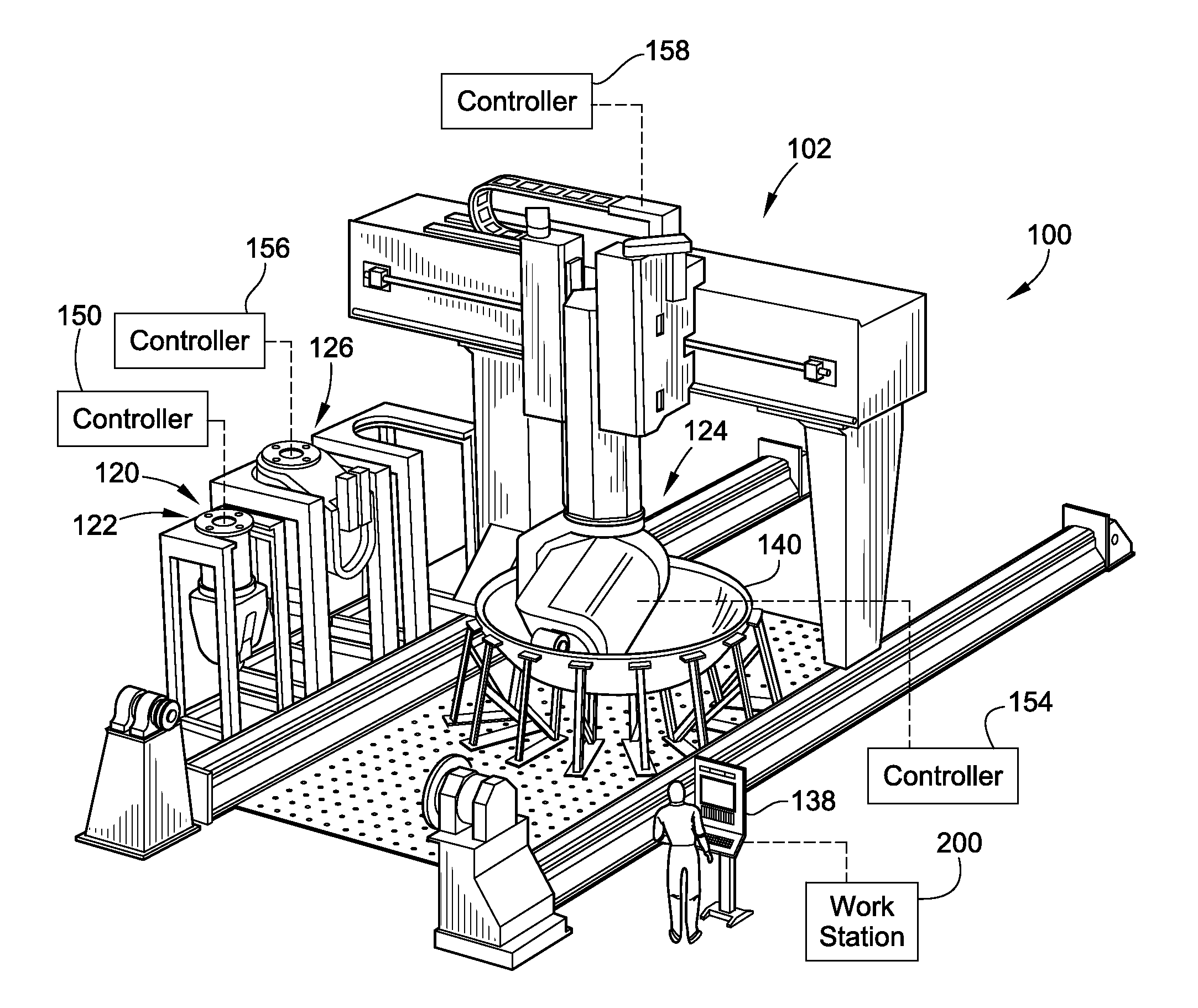
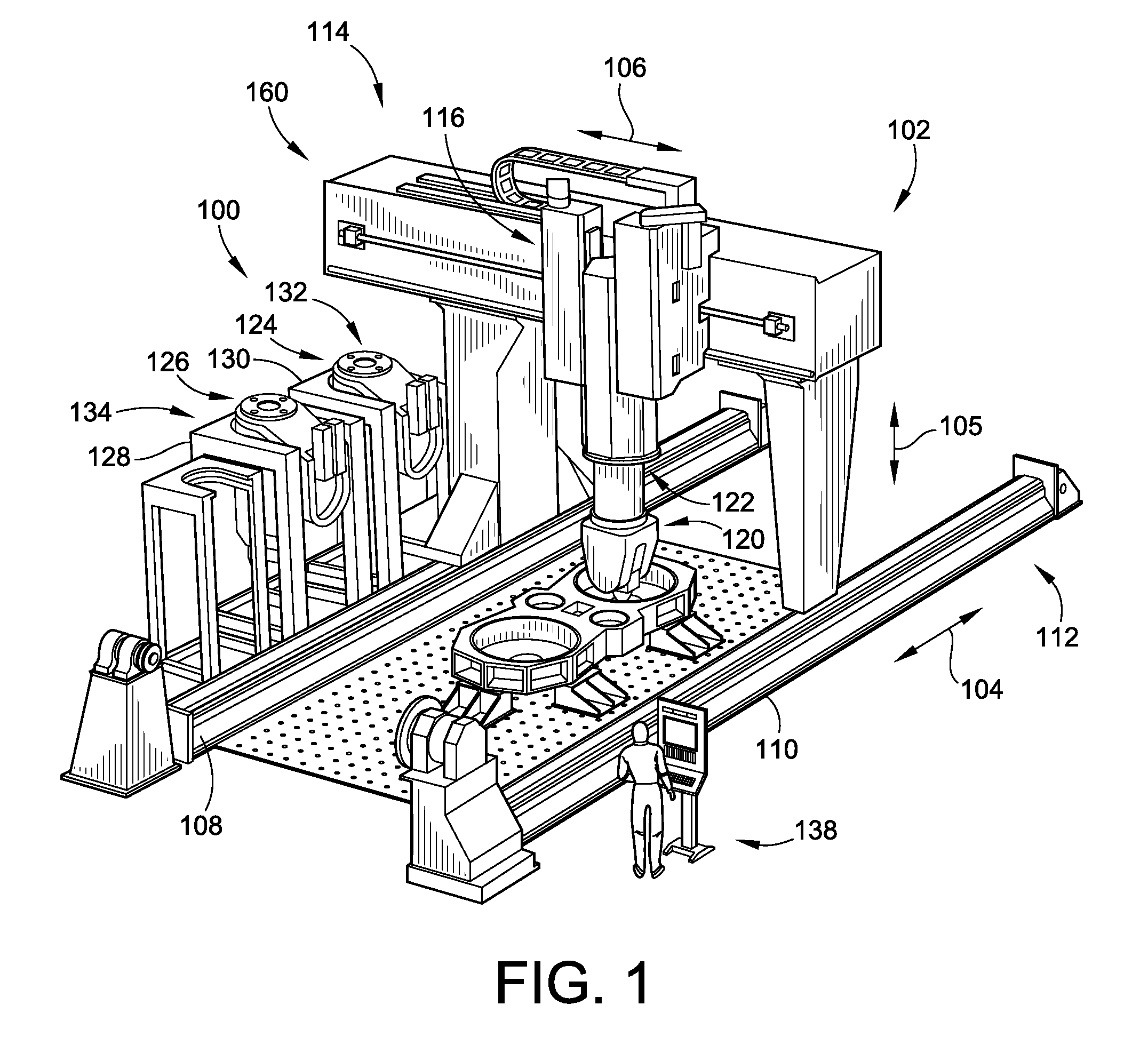
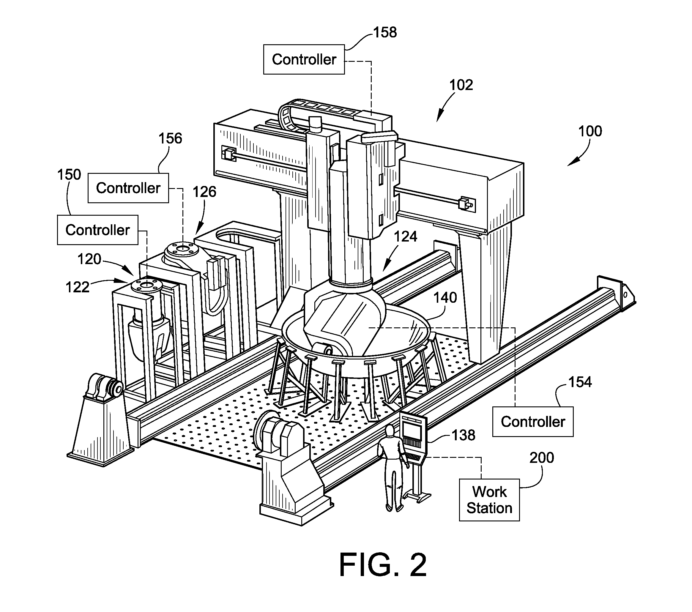
[0026]FIG. 1 illustrates a modular manufacturing apparatus 100 (also referred to as a “modular manufacturing system”) according to an embodiment of the present invention. The modular manufacturing apparatus 100 can be used for various manufacturing processes including cutting or milling operations, as well as composite fiber placement operations (including both fiber tape and fiber tow placement onto a stationary tool, mold or moveable mandrel). The modular manufacturing apparatus 100 is configurable to independently perform these various different manufacturing processes. However, a majority of the primary structures of the modular manufacturing apparatus 100 are reusable for the different manufacturing processes such that the capital investment for providing the devices to perform these various manufacturing processes is significantly reduced.

[0027]In FIG. 1, the modular manufacturing apparatus 100 generally includes a positioning system, illustrated in the form of gantry system 1...


PUM

PropertyMeasurementUnit
frequencyaaaaaaaaaa
shapeaaaaaaaaaa
pressureaaaaaaaaaa

Abstract

A modular manufacturing system and methods of using are provided. The modular manufacturing system includes a plurality of manufacturing heads that perform different manufacturing processes. These heads may include multi-axial machining heads, fiber placement heads including fiber tow and fiber tape lay-up heads. The heads are fixably attachable to a single positioning system that can manipulate the various heads along a plurality of different degrees of freedom relative to a tool or material blank.

Description

CROSS-REFERENCE TO RELATED PATENT APPLICATIONS[0001]This patent application claims the benefit of U.S. Provisional Patent Application No. 61 / 371,236, filed Aug. 6, 2010, and U.S. Provisional Patent Application No. 61 / 406,192, filed Oct. 25, 2010, the entire teachings and disclosures of which are incorporated herein by reference thereto.FIELD OF THE INVENTION[0002]This invention generally relates to machine apparatuses and particularly devices for the purposes of multi-axial metal removal, such as cutting machine tools, and composite fiber tape manufacturing or composite fiber placement manufacturing.BACKGROUND OF THE INVENTION[0003]The practice of manufacturing in aircraft or aerospace fields has become simultaneously complex and diverse requiring multiple disciplines incorporating either metal removal in the form of cutting the desired piece from a larger general shape of the desired metal, or the application of composite fiber in broad bands commonly referred to as “tape” against ...

Claims


Application Information

Patent Timeline
Patent Type & Authority Patents(United States)
IPC IPC(8): B23P19/00G05B19/418B23Q3/155G05B19/414
CPCG05B19/4141B23Q3/15506B29C70/38Y10T483/138Y10T483/17Y10T483/1793Y10T483/1738Y10T409/309296Y10T29/5168G05B19/4145G05B19/418G05B2219/33098G05B2219/33099
Inventor OLDANI, TINO
Owner INGERSOLL MACHINE TOOLS
Why Eureka
Try Eureka