Tunnel mold, system and method for slip forming reinforced concrete structures with exposed rebars

Active Publication Date: 2015-02-17
RAPTOR LLC
View PDF10 Cites 1 Cited by
  • Summary
  • Abstract
  • Description
  • Claims
  • Application Information

AI Technical Summary

Benefits of technology

[0023]In one of the preferred embodiments of this invention, the slip mold comprises a mold cavity for forming a coping for integration of an MSE wall and a road bed. In this preferred embodiment of the invention, the slip-mold includes a series of vibrators positioned within the mold cavity for consolidation of the concrete within the mold cavity, as the slip-mold is progressively advanced over an iron work array. In this embodiment of the invention, the vibrators are positioned to insure consolidation of the concrete within the mold at the margins of the slip formed concrete structure, and proximate to the tunnels through the housing. In each instance, the vibrators provide for a compaction of the concrete within the slip-mold, and, thus, both an enhanced (smooth) finish to the surface of the concrete structure, and improved adhesion of the concrete to the iron word array embedded therein.
[0024]The consolidation of the unset concrete within the mold cavity, proximate to the tunnels through the slip-mold, both increases the density of the concrete at the base of these tunnels, and tends to force the concrete into the tunnels from the mold cavity. In order to minimize the migration of unset concrete into the tunnels from the mold cavity, prior to the consolidation of the concrete, a series of fins are provided, which extend downward from each defining wall of the tunnels, into the unconsolidated concrete in mold cavity. The depth of penetration of the fins into the unconsolidated concrete in the mold cavity is related to the relative time it takes

Problems solved by technology

The consolidation of the unset concrete within the mold cavity, proximate to the tunnels through the slip-mold, both increases

Method used


Image

  • Tunnel mold, system and method for slip forming reinforced concrete structures with exposed rebars
  • Tunnel mold, system and method for slip forming reinforced concrete structures with exposed rebars
  • Tunnel mold, system and method for slip forming reinforced concrete structures with exposed rebars

Examples


Example

[0038]As understood within the context of this invention, the following terms and phrases are intended to have the following meaning unless otherwise indicated.

Glossary of Terms

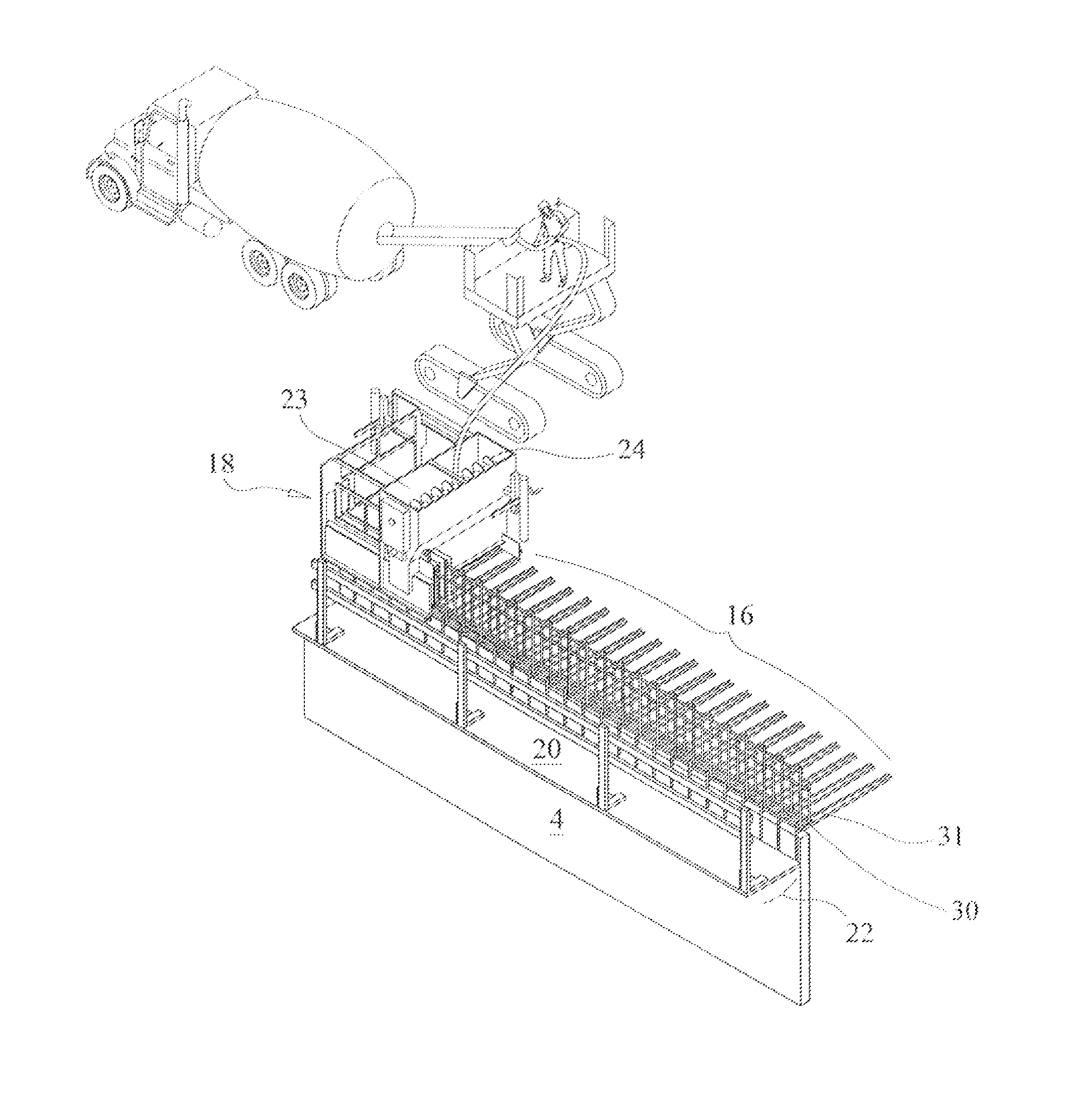
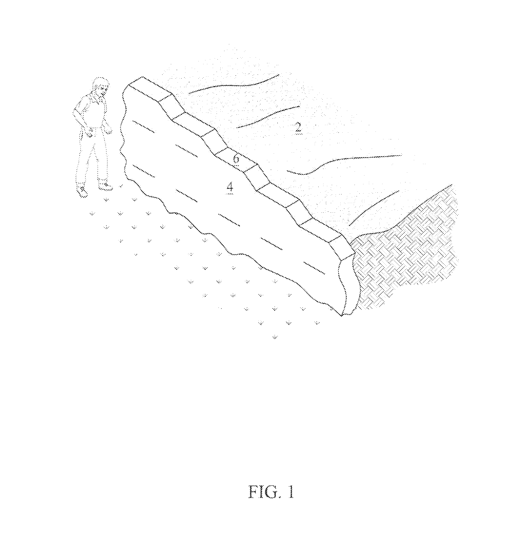
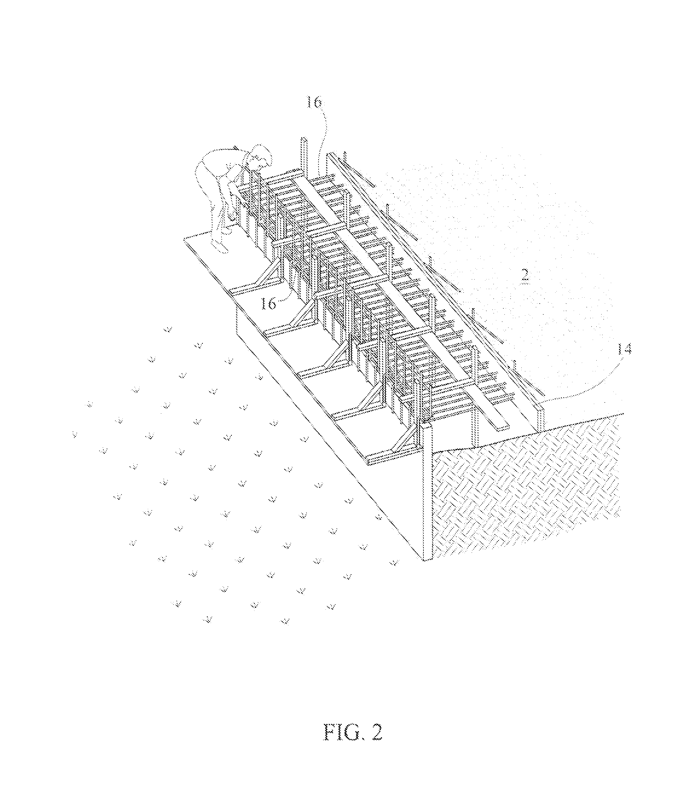
[0039]The phrase “slip forming”, or “horizontal slip forming”, is intended, and used herein, to describe a construction method in which concrete is poured into a continuously moving form (“slip mold”). Slip forming is used for tall structures (such as bridges, towers, buildings, and dams), as well as horizontal structures, such as roadways. Slip forming enables continuous, non-interrupted, cast-in-place “flawless” (i.e. no joints) concrete structures, which have superior performance characteristics to piecewise construction, using discrete form elements. Slip forming relies on the quick-setting properties of concrete, and requires a balance between quick-setting capacity and workability. Concrete needs to be workable enough to be placed into the form and consolidated (via vibration), yet quick-setting enough ...


PUM


Abstract

A slip-mold having a housing having (a) concrete hopper having (b) means for distribution of quick set concrete within said hopper, (c) a mold cavity, and (d) at least one tunnel, in communication with said mold cavity, and extending through said housing from the leading to the trailing end of said housing. The tunnel through the housing is of sufficient height and width, and positioned within said mold housing, to permit rebars, extending from an iron work array, to pass through said mold cavity without becoming embedded in concrete, concurrent with the formation of a slip formed concrete structure on a portion of said iron work array.

Description

CROSS-REFERENCE TO RELATED COMMONLY ASSIGNED APPLICATION[0001]This application is a continuation-in-part of a prior filed, co-pending patent application, entitled Process For Slip Forming Reinforced Bridge Coping With Exposed Rebars, Ser. No. 14 / 071,629 filed on Nov. 4, 2013. Both the prior filed, co-pending patent application and the instant patent application have been commonly assigned to Raptor LLC (A Florida Limited Liability Company)BACKGROUND OF THE INVENTION[0002]1. Field of the Invention[0003]This invention relates to a device, system and method for slip forming reinforced concrete structures. More specifically, this invention is directed to a tunnel mold having at least one tunnel through the mold, to a slip molding system utilizing a tunnel mold and to the method for the slip forming a reinforced concrete structure having a reinforcing iron work array, (also “rebars”), wherein a portion of the iron work array is embedded in a slip formed concrete structure; and, a portion...

Claims


Application Information

Patent Timeline
IPC IPC(8): E01C21/00E01C19/48E01D21/00
CPCE01C19/4866E01D21/00E02D29/0275E01C19/4886E01C7/00E01C11/185E01D19/00
Inventor FREE, PATRICK SHAWNKONTOS, ERIC C
Owner RAPTOR LLC
Why Eureka
Try Eureka