
Eye-tracking visual prosthetic and method

a visual prosthetic and eye-tracking technology, applied in the field of nerve stimulation methods and apparatuses, can solve the problems of slowing the disease progression, inherently hindering, and little hope for maintaining vision

Active Publication Date: 2015-02-17
NUROTONE MEDICAL LTD
View PDF321 Cites 110 Cited by
  • Summary
  • Abstract
  • Description
  • Claims
  • Application Information

AI Technical Summary

Benefits of technology

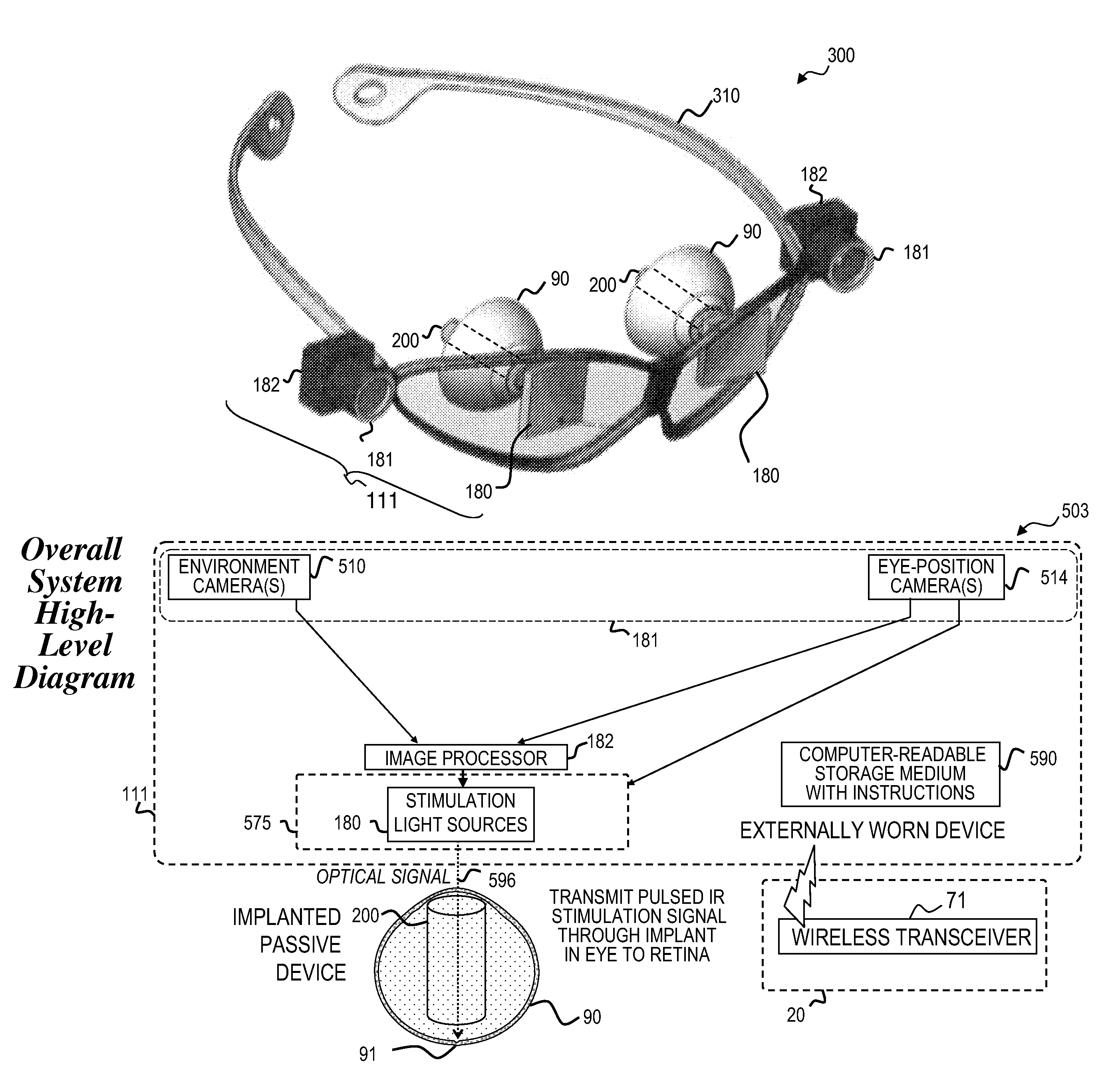
The present invention is a technology that uses infrared lasers to stimulate nerves in the eye using infrared light. This technology allows for highly precise and selective stimulation without damaging the nerves being stimulated or drawing too much power from the power supply of the prosthesis. The invention also includes a camera and processor all packaged into eyeglasses-like device or other headwear for convenient use. Additionally, the invention includes an ocular implant that focuses and directs the path of the infrared stimulation light towards the desired nerves. The device(s) project the stimulation light towards the back of the eye while the camera or other imager obtains images of the tissue at the back of the eye, which can be used to assist the focusing of the stimulation light. The invention is aimed at providing a better understanding and control of the stimulation process for research and clinical applications.

Problems solved by technology

For many patients suffering from retinal degenerative diseases such as advanced or age-related macular degeneration (AMD) and retinitis pigmentosa (RP) there has been little hope for maintaining vision.
There are presently no cures for these debilitating diseases, and, at best, current treatments only slow the disease progression.
The overall social and economic impact of AMD and RP is immense and the importance of treating blindness is profound as this is a problem of significant scope and breadth.
Advanced macular degeneration and retinitis pigmentosa are both degenerative diseases that degrade vision in patients and eventually can lead to blindness.
These devices apply an electric current pulse to stimulate the neurons of the visual system which is inherently hindered by a lack of spatial selectivity.
Electrical current spread leads to imprecise nerve stimulation and limits the ability of the neuroprosthesis to restore function.
The limitation of spatial selectivity is based on fundamental physical principles of electrical stimulation.
The technology is further limited by the fact that physical contact is required with tissue, which can lead to damage over time.
Implantation of a complex powered device in very close proximity to sensitive neural tissue forms a significant drawback to this approach, making it impossible to update the technology without further risky surgeries.
Electrical stimulation represents a major challenge in developing implantable devices with long-term system performance while reducing their overall size.
Since no micro-cables are required to be attached to the device, and its overall form and edges are rounded, the device is not expected to stress the retina during chronic implantation.
Electrical stimulation, as described in the above devices and patents, is limited since the spread of electricity does not allow separate or independent stimulation of individual retinal nerve cells or even small-enough groups of nerve cells for sharp or clear vision.
This electrical-stimulation technology is severely limited, as electricity spreads in human tissue and thus will severely limit the number of stimulation sites.
Electrical stimulation thus greatly limits the number of sites that could be separately stimulated.
Additionally, the electrical-stimulation approach will require implantation of a powered (e.g., an electrically powered) device, which has significantly difficult issues associated with obtaining power into the eye and using the power by devices in the eye.
This approach is limited as there is a high degree of integration on the periphery of the fovea that, again, will severely limit resolution.
This area may have some potential, however it will require significant development work, it involves injecting a virus into nerve tissue (which may have significant side effects and FDA-approval issues), and the virus is only partially taken up by nerve cells.

Method used


Image

  • Eye-tracking visual prosthetic and method
  • Eye-tracking visual prosthetic and method
  • Eye-tracking visual prosthetic and method

Examples


Embodiment Construction

[0077]Although the following detailed description contains many specifics for the purpose of illustration, a person of ordinary skill in the art will appreciate that many variations and alterations to the following details are within the scope of the invention. Very narrow and specific examples are used to illustrate particular embodiments; however, the invention described in the claims is not intended to be limited to only these examples, but rather includes combinations and subcombinations of features shown in the various figures and descriptions. The invention includes the full scope of the attached claims. Accordingly, the following preferred embodiments of the invention are set forth without any loss of generality to, and without imposing limitations upon the claimed invention. Further, in the following detailed description of the preferred embodiments, reference is made to the accompanying drawings that form a part hereof, and in which are shown by way of illustration specific...


PUM


Abstract

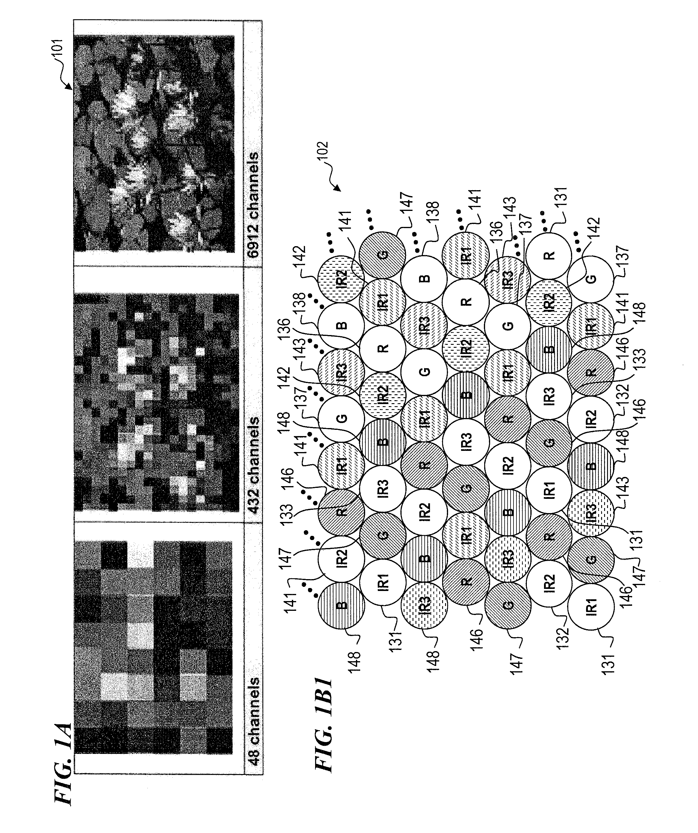
An improved prosthesis and method for stimulating vision nerves to obtain a vision sensation that is useful for the patient that has lost vision due to AMD, RP, and other diseases. The invention utilizes infrared light to cause action potentials in the retinal nerves similar to those which result from rods and cones stimulated by visible light in healthy retinas. In some embodiments, the invention provides a prosthesis that generates a stimulation pattern of infrared light from an external stimulator array through the eye and focusing the stimulation pattern of infrared light on the retina, especially the fovea. Some embodiments the invention provides improved resolution down to a group of nerves, or even the individual nerve level, with sufficient energy density so as to cause a desired action potential.

Description

CROSS-REFERENCE TO RELATED APPLICATIONS[0001]This application claims priority benefit under 35 U.S.C. §119(e) of U.S. Provisional Patent Application No. 61 / 514,894 filed Aug. 3, 2011 by Michael E. Friend et al., titled “SIGHT-RESTORING VISUAL PROSTHETIC AND METHOD USING INFRARED NERVE-STIMULATION LIGHT”, which is incorporated herein by reference in its entirety.[0002]This invention is related to the following prior applications and patents:[0003]U.S. patent application Ser. No. 13 / 525,268 filed on even date herewith (Jun. 15, 2012), titled “SIGHT-RESTORING VISUAL PROSTHETIC AND METHOD USING INFRARED NERVE-STIMULATION LIGHT”;[0004]U.S. Provisional Patent Application No. 60 / 715,884 filed Sep. 9, 2005, titled “Apparatus and Method for Optical Stimulation of Nerves”;[0005]U.S. patent application Ser. No. 11 / 257,793 filed Oct. 24, 2005, titled “Apparatus for Optical Stimulation of Nerves and Other Animal Tissue” (now U.S. Pat. No. 7,736,382 issued Jun. 15, 2010);[0006]U.S. Provisional Pa...

Claims


Application Information

Patent Timeline
Patent Type & Authority Patents(United States)
IPC IPC(8): A61N5/067A61N5/06
CPCA61N5/06A61N5/0622A61N2005/0659A61N2005/067A61N5/067
Inventor FRIEND, MICHAEL E.HU, YONGDANLEMAIRE, CHARLES A.
Owner NUROTONE MEDICAL LTD
Learn More