

Optical isolators and methods of manufacture
a technology of optical isolators and isolators, which is applied in the direction of generators/motors, polarising elements, instruments, etc., can solve the problems of reducing the performance of the system, adversely affecting the transmission source, introducing optical signal loss, etc., to facilitate chemical bonding, facilitate bonding, and facilitate the effect of bonding
- Summary
- Abstract
- Description
- Claims
- Application Information
AI Technical Summary
Benefits of technology
Problems solved by technology
Method used
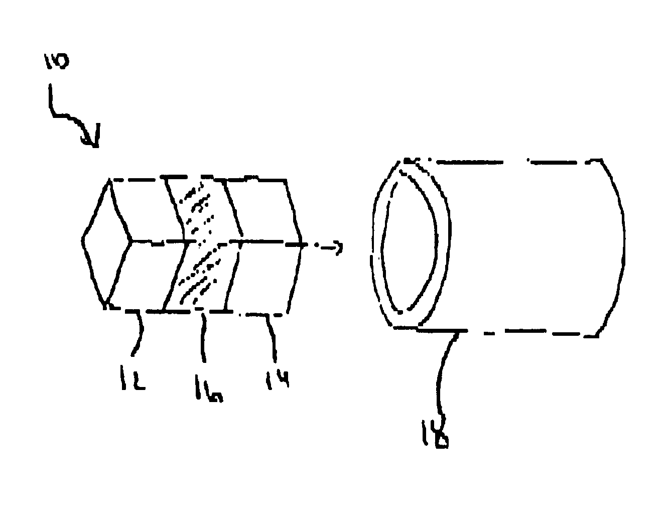
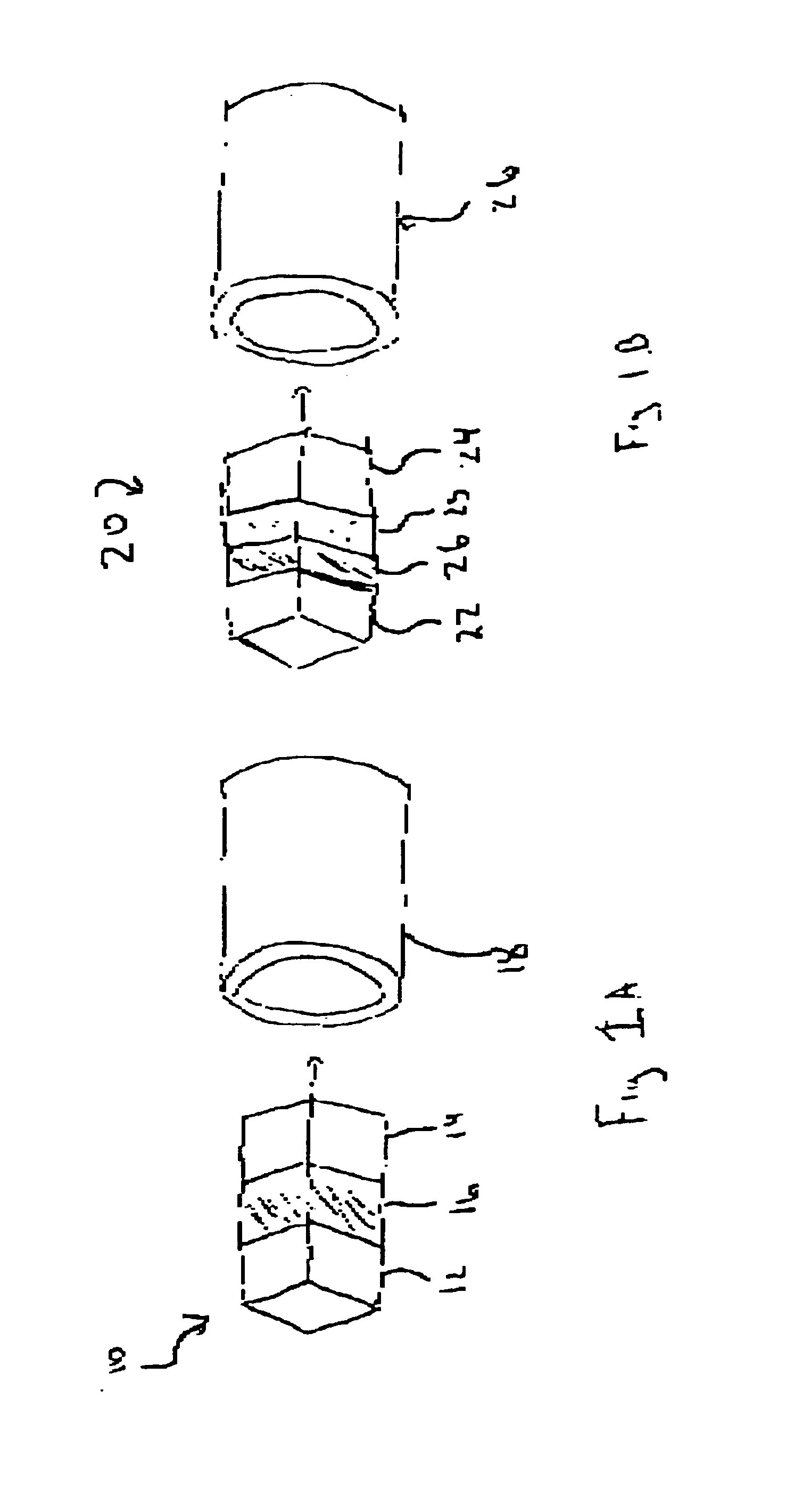
Image

Examples
example 2
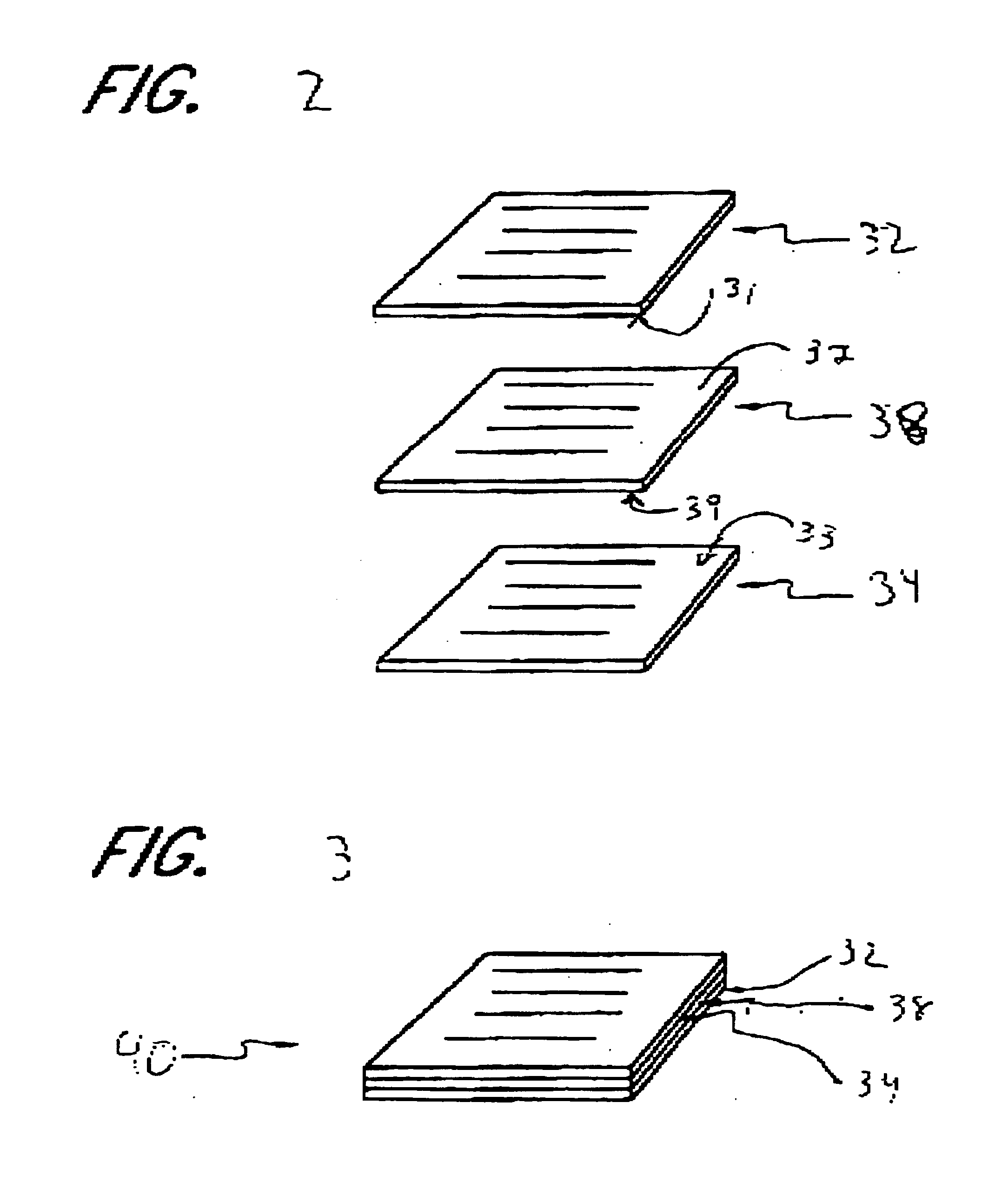
This example demonstrates that isolator cores comprising Polarcor.TM. glass sheets sandwiched together with a Faraday rotator material sheet can be bonded together and diced into isolator cores without delamination. Two Polarcor.TM. glass sheets previously polished to less than 1 micron flatness and AR coated were pretreated by coating with lithium metal by thermal evaporation under vacuum and heat treated at 200.degree. C. for 24 hours. The lithium coated Polarcor.TM. sheets along with a flat, AR-coated bismuth iron garnet (BIG, purchased from MGC) sheet were cleaned with a detergent solution (Microclean CA05), rinsed in water and soaked in 10 volume % nitric acid solution for 1 hour. The acid-soaked samples were rinsed in water and then soaked in a 15 volume % ammonium hydroxide solution for 1 hour. The samples were rinsed again, and the bonding surfaces were maintained in a wet condition, stacked so that the Polaror.TM. sheets sandwiched the Faraday rotator sheet, and bonded unde...
PUM
| Property | Measurement | Unit |
|---|---|---|
| Curie temperature | aaaaa | aaaaa |
| roughness | aaaaa | aaaaa |
| roughness | aaaaa | aaaaa |
Abstract
Description
Claims
Application Information