
Magnetic controlled power generator

a power generator and magnetic control technology, applied in the direction of electrical equipment, dynamo-electric machines, gymnastics, etc., can solve the problems of difficult to link up to external digital signals, difficult to assemble and repair components, and inability to achieve computerization and digitization. , to achieve the effect of easy assembly and disassembly, and easy manufacture and maintenan

Active Publication Date: 2015-02-17
CHI HUA FITNESS
View PDF11 Cites 16 Cited by
  • Summary
  • Abstract
  • Description
  • Claims
  • Application Information

AI Technical Summary

Benefits of technology

The present invention provides a magnetic controlled power generator that can be easily assembled and disassembled for easy manufacture and maintenance. The generator is simple in installation, lightweight, and has a radial displacement for magnetic flux control that allows for continuous adjustment of load resistance, reducing cost and weight. The technical effects are improved manufacturing and maintenance, simplified installation, and lightweight components that achieve continuous adjustment of the load resistance through magnetic flux control.

Problems solved by technology

1. If the magnetic controlled loading device, power generator and flywheel have poor compatibility, the magnetron load regulation, power generation efficiency and flywheel inertia forces will affect sports equipment and thus it is difficult to assemble and repair the components.
2. If the loading portion uses permanent magnets as its magnetic field source, then it is very difficult to link up to external digital signals, and thereby unable to attain the goal of computerization and digitization, unless there is a motor and motor controller to change the relative location of the magnets and conductors, or utilizing magnetic wire coils and external power sources to overcome these problems.

Method used


Image

  • Magnetic controlled power generator
  • Magnetic controlled power generator
  • Magnetic controlled power generator

Examples


Embodiment Construction

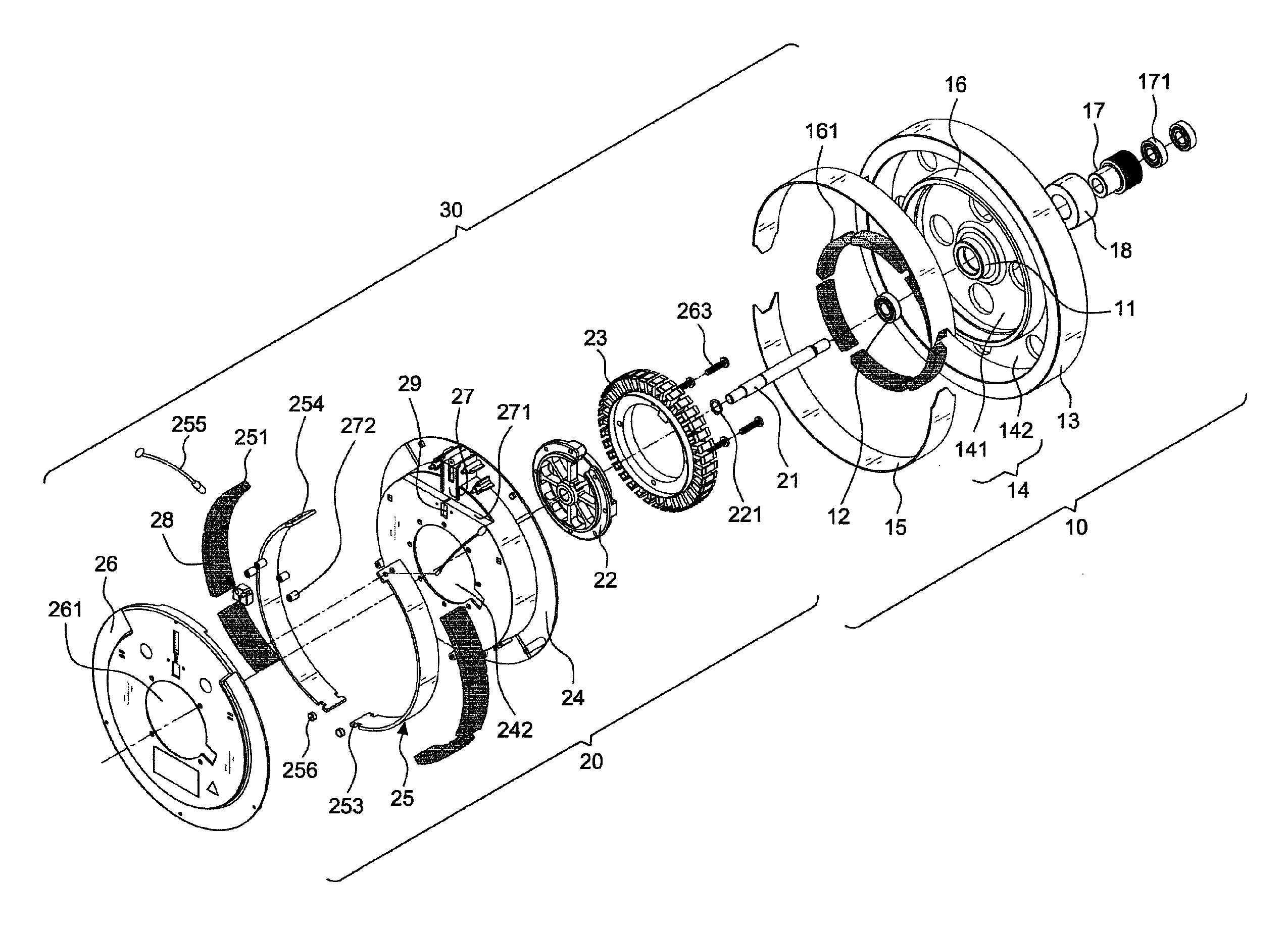
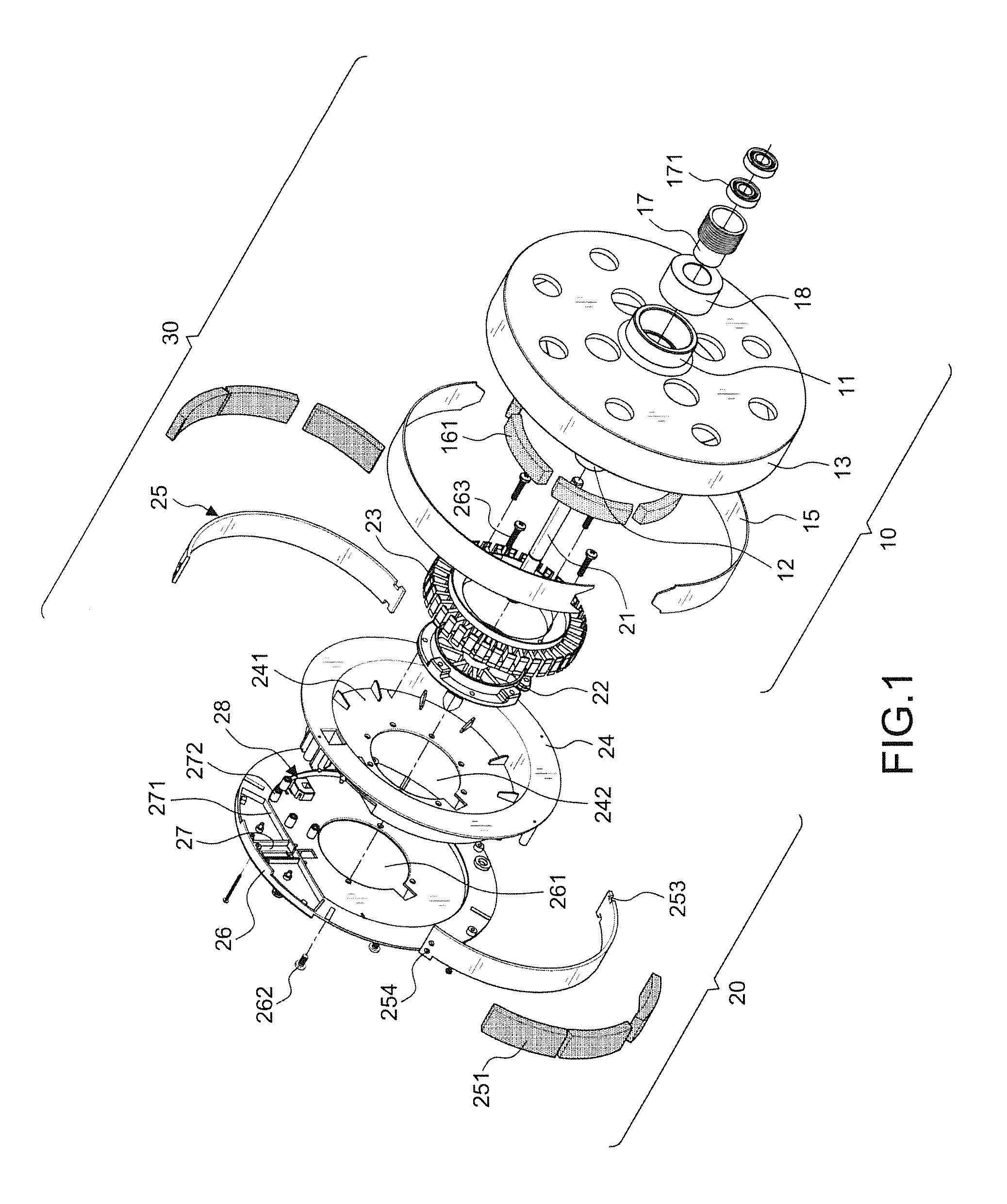
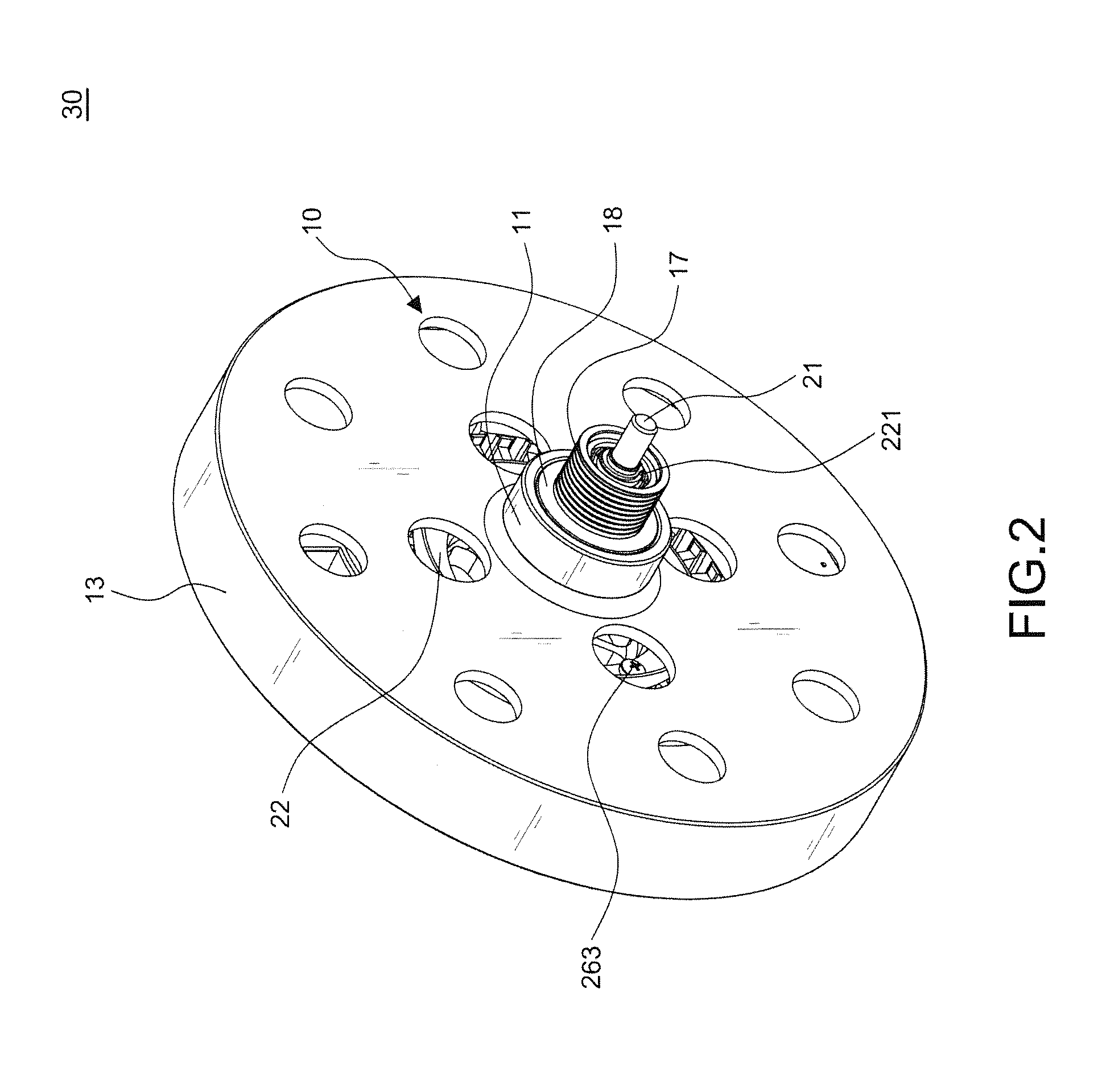
[0024]Referring to FIGS. 1 through 8, the preferred embodiment of a magnetic controlled power generator in accordance with the present invention comprises the following components as discussed in detail below.

[0025]A flywheel device 10 having a first bearing 12 disposed within a hub 11 of the flywheel device 10, the flywheel device 10 being recessed under a wheel rim 13, which forms an accommodating space 14, a metal conductor 15 being mounted on an inner surface of the wheel rim 13; a magnetic controlled loading device 20 arranged within the accommodating space 14 of the flywheel device 10 to form a magnetic controlled power generator 30. The above features are disclosed in prior art and thus will not be described in details here.

[0026]The present invention is characterized in that the flywheel device 10 includes an annular body 16 being arranged within the accommodating space 14 and being concentric with an axis of the hub 11 to form an inner annular groove 141 and outer annular g...


PUM


Abstract

A magnetic controlled power generator provides a magnetic controlled loading device, power generator and flywheel device to form two independent modules which are easily assembled and disassembled for easy manufacture and maintenance. Besides, the magnetic controlled power generator has simple installation and lightweight components to generate a radial displacement for magnetic flux control, achieving continuous adjustment of the load resistance, thereby having the effect of reducing the cost and weight.

Description

BACKGROUND OF THE INVENTION[0001]1. Field of the Invention[0002]The invention relates to a magnetic controlled power generator, to rearrange the relative location of the magnetic controlled loading device, power generator, and flywheel device to form two independent modules for easy assembly and disassembly.[0003]2. Description of the Related Art[0004]Sports equipment with a magnetic controlled power generator can produce flywheel inertia force, power generation and magnetron load regulation. The magnetic controlled power generator includes a magnetic controlled loading device, power generator and flywheel.[0005]A magnet rotates with the flywheel to form a magnetic circuit of the armature core for a coil of the armature core producing electricity, which is the principle of a permanent-magnet alternating current generator. The magnetic controlled power generator uses this principle by making the flywheel as the source for the alternating current generator, so that the voltage produce...

Claims


Application Information

Patent Timeline
IPC IPC(8): H02K7/02
CPCH02K7/02A63B21/0051A63B21/0053A63B21/157A63B21/225A63B24/0087A63B2225/30
Inventor HSU, CHENG-CHIEN
Owner CHI HUA FITNESS
Learn More