Dynamic comparator with equalization function

a dynamic comparator and function technology, applied in the field of dynamic comparators, can solve problems such as the design trade-off between speed and accuracy, and achieve the effects of less recovery time, no static power consumption, and enhanced operation speed of the dynamic comparator

Active Publication Date: 2015-02-17
IND TECH RES INST
View PDF5 Cites 3 Cited by
  • Summary
  • Abstract
  • Description
  • Claims
  • Application Information

AI Technical Summary

Benefits of technology

[0012]Also, the present disclosure provides a dynamic comparator with equalization function that reduces the recovery time of output common-mode voltage in the comparison mode according to the equalized voltage generated during equalization.
[0014]Compared to the prior art, the present disclosure provides a dynamic equalizer which resolves DC power consumption problem in traditional static equalizer. In the dynamic comparator with dynamic equalization function according to the present disclosure, the dynamic transconductance circuit can perform equalization in the reset mode, such that the bias voltages of the two output terminals of the dynamic comparator are equalized to a balanced state without the need for additional direct current, thereby have no static power consumption. Operating at comparison mode, the dynamic transconductance circuit is switched to perform transconductance, that is, convert signal from voltage to current. Since the two output terminals of the dynamic comparator are already biased to specific voltages under the reset mode, it requires less recovery time to reach the output common-mode voltage condition before signal regeneration. Thus, the operating speed of the dynamic comparator is enhanced.

Problems solved by technology

The comparator structure has the characteristics of a high-impedance input, but its high transistor stack limits the supply voltage, and the size of the tail current is determined by only one transistor, resulting in the design trade-off between speed and accuracy.

Method used


Image

  • Dynamic comparator with equalization function
  • Dynamic comparator with equalization function
  • Dynamic comparator with equalization function

Examples


Embodiment Construction

[0020]In the following detailed description, for purposes of explanation, numerous specific details are set forth in order to provide a thorough understanding of the disclosed embodiments. It will be apparent, however, that one or more embodiments may be practiced without these specific details. In other instances, well-known structures and devices are schematically shown in order to simplify the drawing.

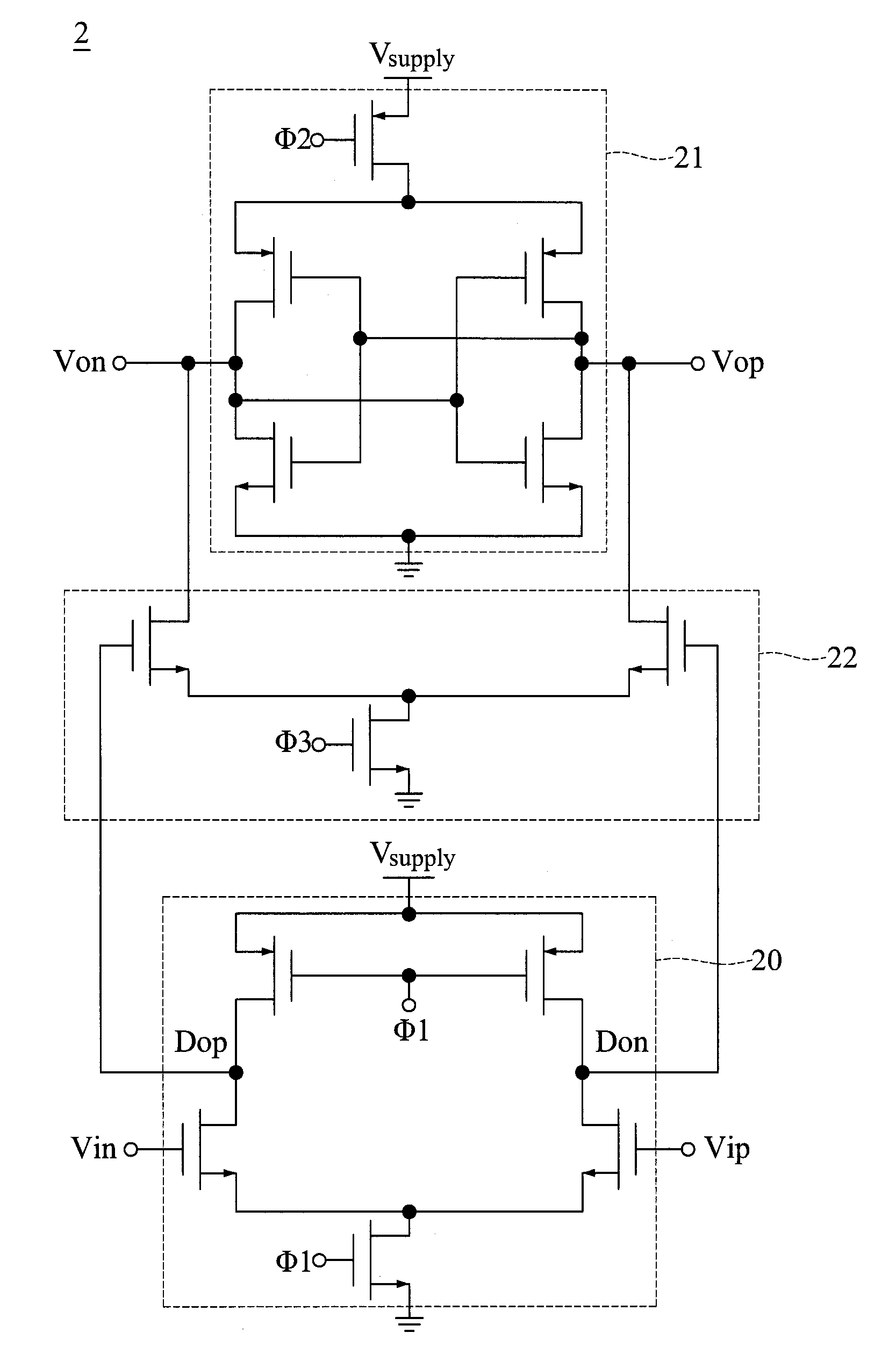
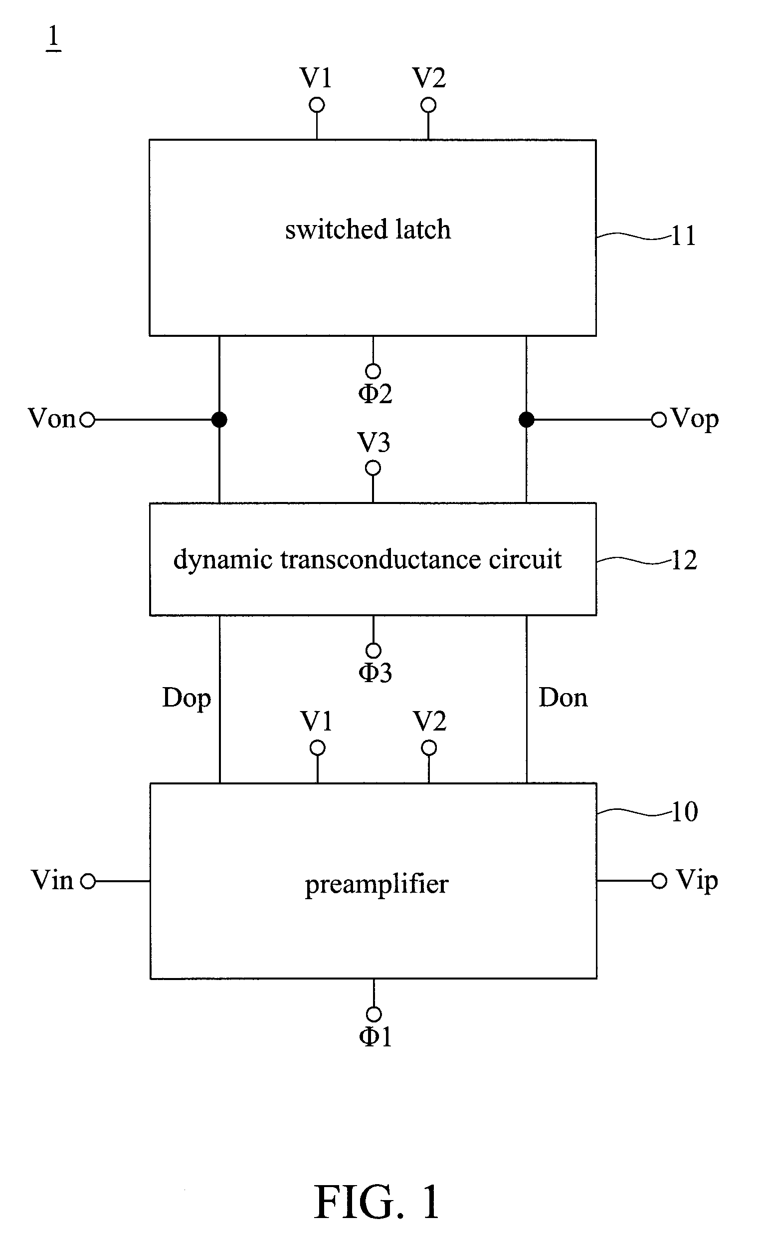
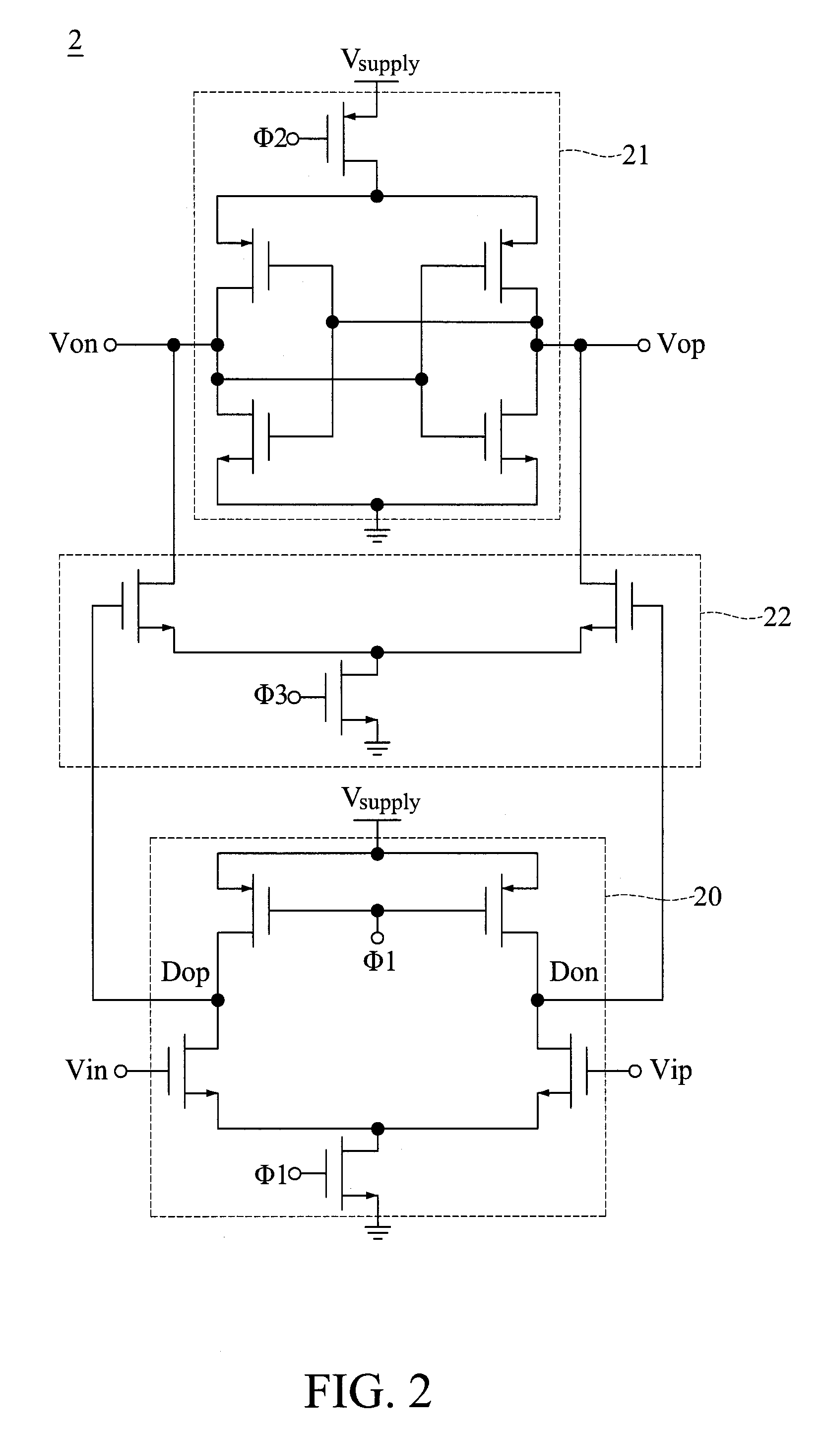
[0021]Referring to FIG. 1, a schematic diagram depicting the system of a dynamic comparator 1 with equalization function in accordance with the present disclosure is shown. The dynamic comparator 1 compares two input voltages and generates an output signal as the comparison result of the dynamic comparator 1. The power consumption and operating speed of the dynamic comparator 1 are improved by a dynamic transconductance circuit with equalization function in the present disclosure. The dynamic comparator 1 includes a preamplifier 10, a switched latch 11, and a dynamic transconductanc...


PUM


Abstract

The present disclosure provides a dynamic comparator with equalization function including a preamplifier, switched latch and dynamic transconductance circuit. The preamplifier amplifies input signals of the dynamic comparator. The dynamic transconductance circuit is inserted between the preamplifier and the switched latch for operating in a reset mode or a comparison mode. When operating in the reset mode, the dynamic transconductance circuit in conjunction with the switched latch performs voltage equalization of output signals of the switched latch, or when operating in the comparison mode, the dynamic transconductance circuit in conjunction with the switched latch receives the output signals generated by the preamplifier and carries out signal transconductance. The switched latch generates output signals as a comparison result of the dynamic comparator based on the transconductance signals generated by the dynamic transconductance circuit. The present disclosure provides a dynamic comparator that reduces the power consumption and increasing the operating speed.

Description

CROSS-REFERENCE TO RELATED APPLICATIONS[0001]This application claimed priority to Taiwanese Patent Application No. 101135481, filed on Sep. 27, 2012. The entirety of the above-mentioned patent application is hereby incorporated by reference herein and made a part of this specification.BACKGROUND[0002]1. Technical Field[0003]The present invention relates to dynamic comparators, and, more particularly, to a dynamic comparator with equalization function.[0004]2. Description of Related Art[0005]Comparators that compare the difference between input signals and output the result of the comparison have been widely used in electronic equipment or electronic devices.[0006]For example, a general dynamic comparator is dynamically switched between reset and comparing mode. The dynamic comparator comprises a preamplifier and a switched latch. The preamplifier is used to amplify input signals and applies its output signals to the switched latch, so that the sensitivity of the comparator can be im...

Claims


Application Information

Patent Timeline
Patent Type & Authority Patents(United States)
IPC IPC(8): H03K5/22
CPCH03K5/22
Inventor CHEN, BO-WEI
Owner IND TECH RES INST
Why Eureka
Try Eureka