Light-emitting device
a technology of light-emitting devices and threshold voltages, which is applied in static indicating devices, electroluminescent light sources, instruments, etc., can solve the problems that the generation of uneven luminance of light-emitting elements due to threshold voltage variations cannot be prevented, and the threshold voltage cannot be acquired. the effect of reducing the variation of luminance between pixels
- Summary
- Abstract
- Description
- Claims
- Application Information
AI Technical Summary
Benefits of technology
Problems solved by technology
Method used
Image
Examples
embodiment 1
(Embodiment 1)
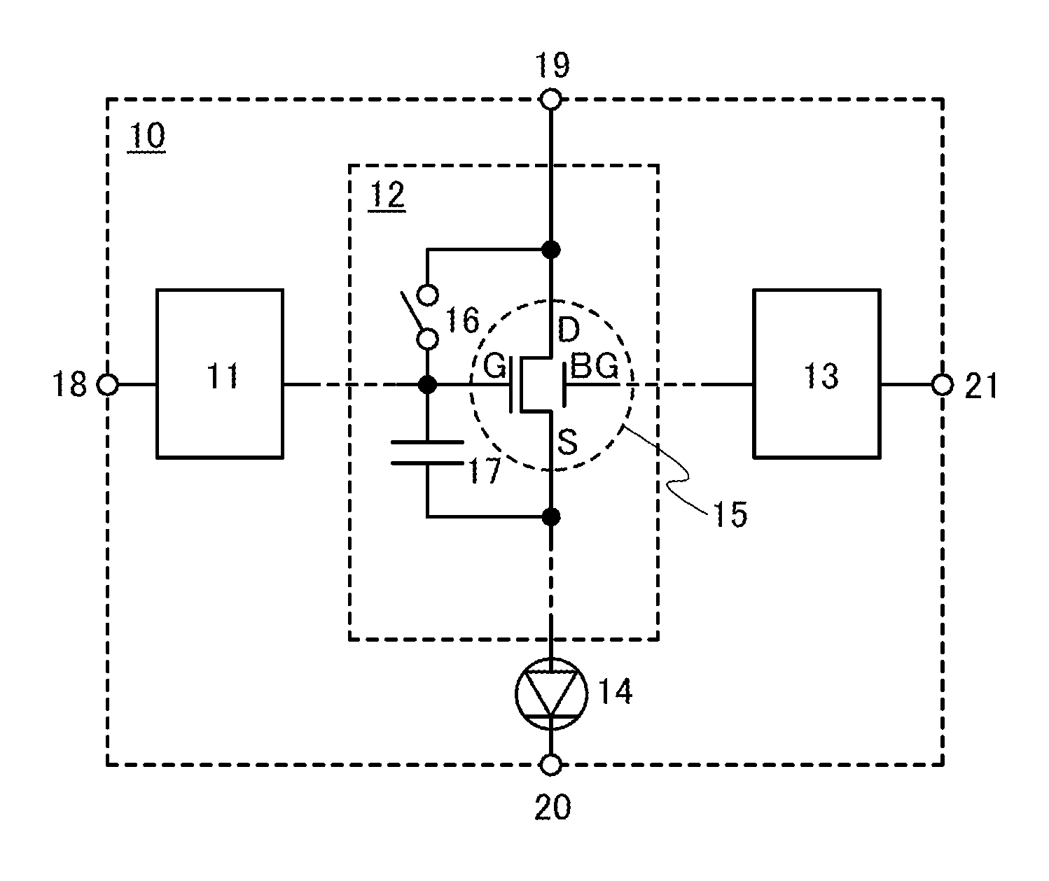
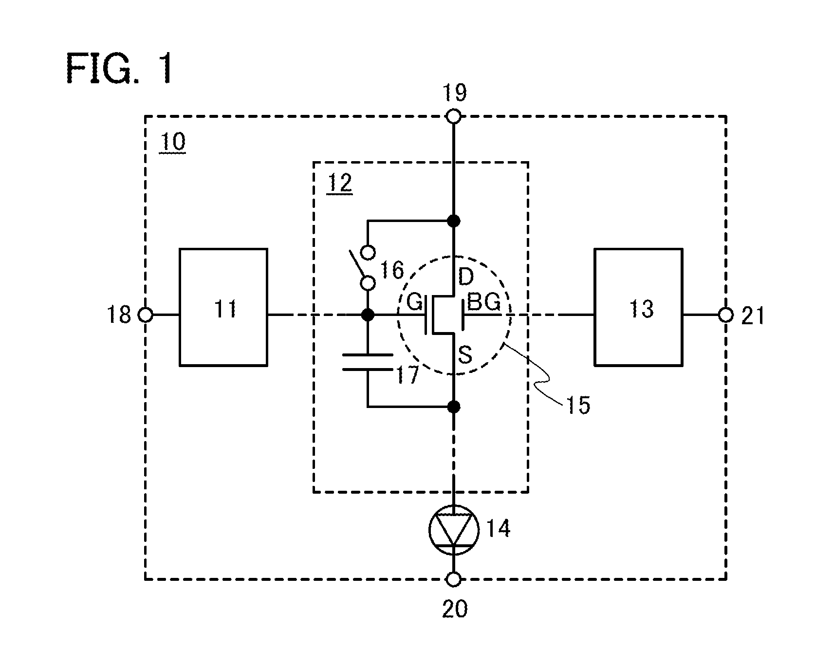
[0033]FIG. 1 illustrates the structure of a pixel included in a light-emitting device according to one embodiment of the present invention. A pixel 10 in FIG. 1 includes a switch 11, a circuit 12 for controlling the amount of current in response to an image signal, a switch 13, and a light-emitting element 14 supplied with the current from the circuit 12.
[0034]Specifically, the switch 11 controls whether an image signal supplied to a terminal 18 is supplied to the circuit 12. For example, the switch 11 can be one or more transistors. Alternatively, the switch 11 may be a capacitor instead of one or more transistors.
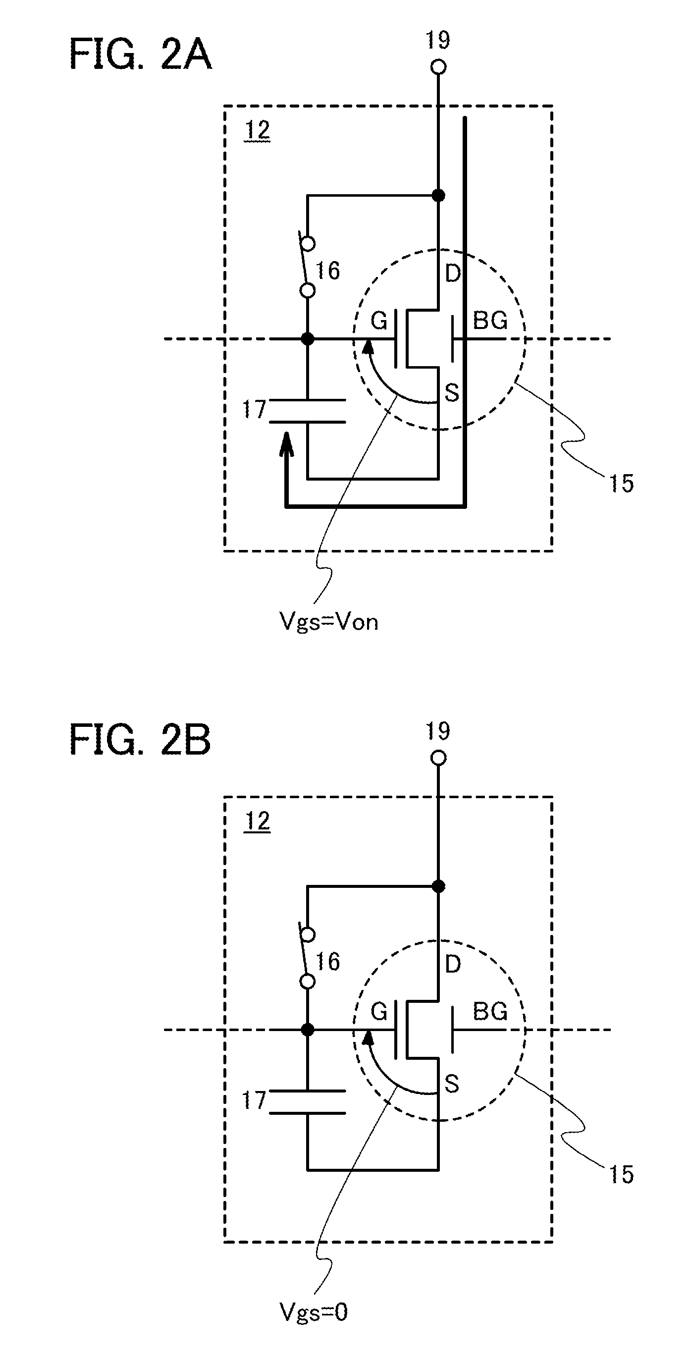
[0035]The circuit 12 includes a transistor 15 whose drain current is supplied to the light-emitting element 14, a switch 16, and a capacitor 17. The switch 16 selects conduction or non-conduction between a gate electrode (represented by G) and a drain terminal (represented by D) of the transistor 15, that is, controls connection between the gate electrode an...
embodiment 2
(Embodiment 2)
[0057]FIG. 4 illustrates a specific structure example of a pixel in a light-emitting device according to one embodiment of the present invention.
[0058]As in FIG. 1, the pixel 10 in FIG. 4 includes the switch 11, the circuit 12, the switch 13, and the light-emitting element 14. In the pixel 10 in FIG. 4, the switch 11 is a transistor 30. Further, the circuit 12 includes the transistor 15, the capacitor 17, transistors 31 to 36, and a capacitor 38. The transistor 31 corresponds to the switch 16 in FIG. 1. The switch 13 is a transistor 37.
[0059]Note that in FIG. 4, the transistor 15 is an n-channel transistor.
[0060]Specifically, in the pixel 10 in FIG. 4, a gate electrode of the transistor 30 is connected to a scan line GLa. One of a source terminal and a drain terminal of the transistor 30 is connected to the signal line SL. The other of the source terminal and the drain terminal of the transistor 30 is connected to the gate electrode of the transistor 15. A gate electro...
embodiment 3
(Embodiment 3)
[0096]FIG. 10 illustrates a specific structure example of a pixel in a light-emitting device according to one embodiment of the present invention.
[0097]As in FIG. 1, the pixel 10 in FIG. 10 includes the switch 11, the circuit 12, the switch 13, and the light-emitting element 14. In the pixel 10 in FIG. 10, the switch 11 is a transistor 51. Further, the circuit 12 includes the transistor 15, the capacitor 17, transistors 52 to 55, and capacitors 57 and 58. The transistor 52 corresponds to the switch 16 in FIG. 1. The switch 13 is a transistor 56.
[0098]Note that in FIG. 10, the transistor 15 is an n-channel transistor.
[0099]Specifically, in the pixel 10 in FIG. 10, a gate electrode of the transistor 51 is connected to the scan line GLa. One of a source terminal and a drain terminal of the transistor 51 is connected to the signal line SL. The other of the source terminal and the drain terminal of the transistor 51 is connected to the gate electrode of the transistor 15 an...
PUM
 Abstract
Description
Claims
Application Information
 - R&D
- Intellectual Property
- Life Sciences
- Materials
- Tech Scout
- Unparalleled Data Quality
- Higher Quality Content
- 60% Fewer Hallucinations
Browse by: Latest US Patents, China's latest patents, Technical Efficacy Thesaurus, Application Domain, Technology Topic, Popular Technical Reports.
© 2025 PatSnap. All rights reserved.Legal|Privacy policy|Modern Slavery Act Transparency Statement|Sitemap|About US| Contact US: help@patsnap.com


