Pin oven with a continuous U-shaped duct

a technology of u-shaped ducts and ovens, which is applied in the field of ovens, can solve the problems of high energy consumption, both in terms of natural gas used to fuel air heaters and electricity used to operate blower motors and conveyor motors, and achieve the effect of facilitating uniform air flow

Active Publication Date: 2015-02-24
INT THERMAL SYST
View PDF22 Cites 8 Cited by
  • Summary
  • Abstract
  • Description
  • Claims
  • Application Information

AI Technical Summary

Benefits of technology

[0013]In another embodiment, the oven is configured to provide a velocity of air directed at the container throughout the continuous duct path at a rate of more than six thousand and one feet per minute and not more than eight thousand feet per minute. In a further embodiment, the oven is configured to provide a temperature difference between any two points within the interior space of the U-shaped duct path controlled to plus or minus two degrees Fahrenheit, by a uniform air flow throughout the oven. The uniform air flow is facilitated by the sizing and spacing of the various circular orifices and slotted orifices in the continuous duct path.
[0014]The apparatus of the present invention is of a construction which is both durable and long lasting, and which will require little or no maintenance to be provided by the user throughout its operating lifetime. Finally, all of the aforesaid advantages and objectives are achieved without incurring any substantial relative disadvantage.

Problems solved by technology

Accordingly, energy consumption, both in terms of natural gas used to fuel the air heaters and electricity to operate the blower motors and conveyor motors is very substantial.

Method used


Image

  • Pin oven with a continuous U-shaped duct
  • Pin oven with a continuous U-shaped duct
  • Pin oven with a continuous U-shaped duct

Examples


Embodiment Construction

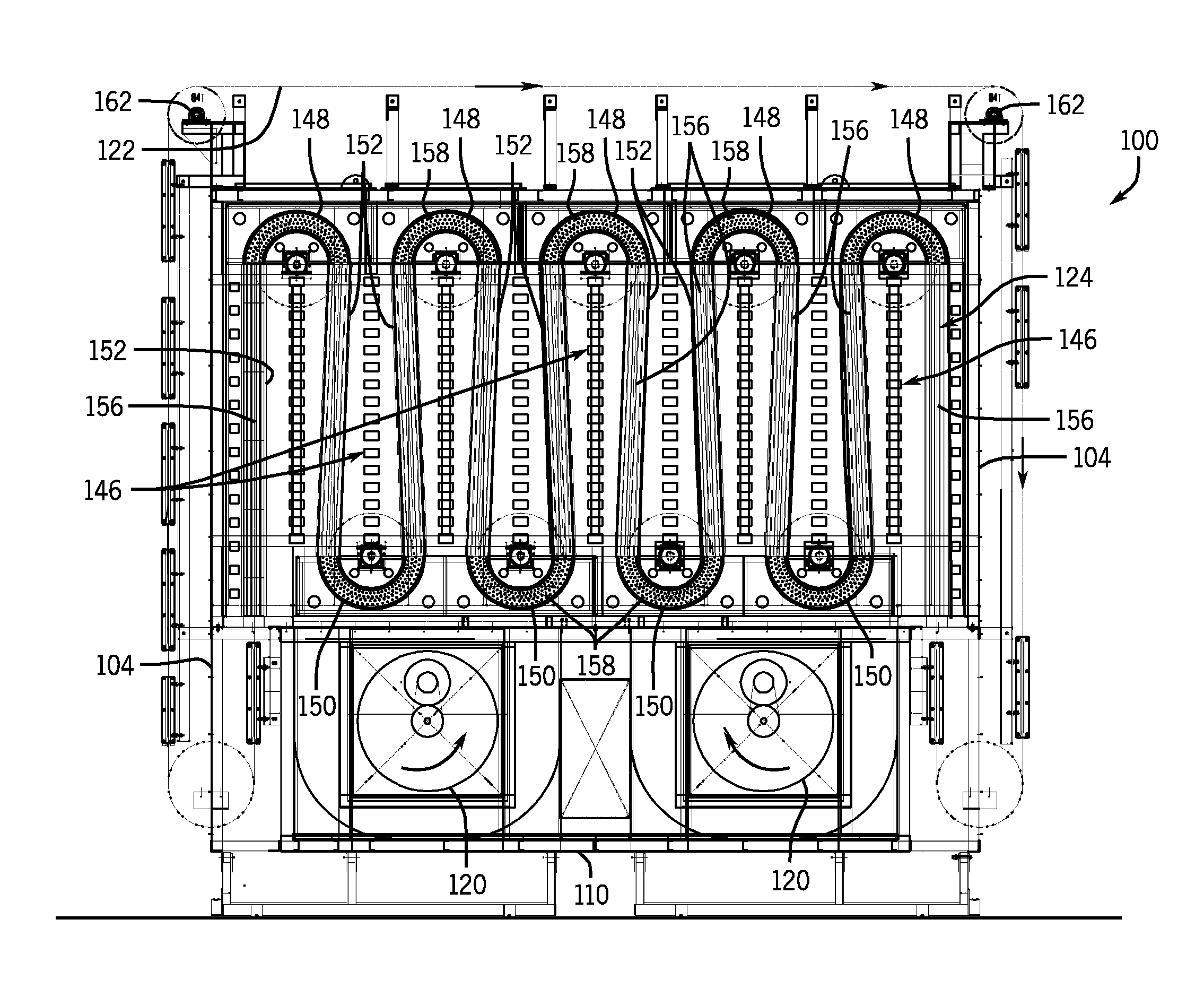
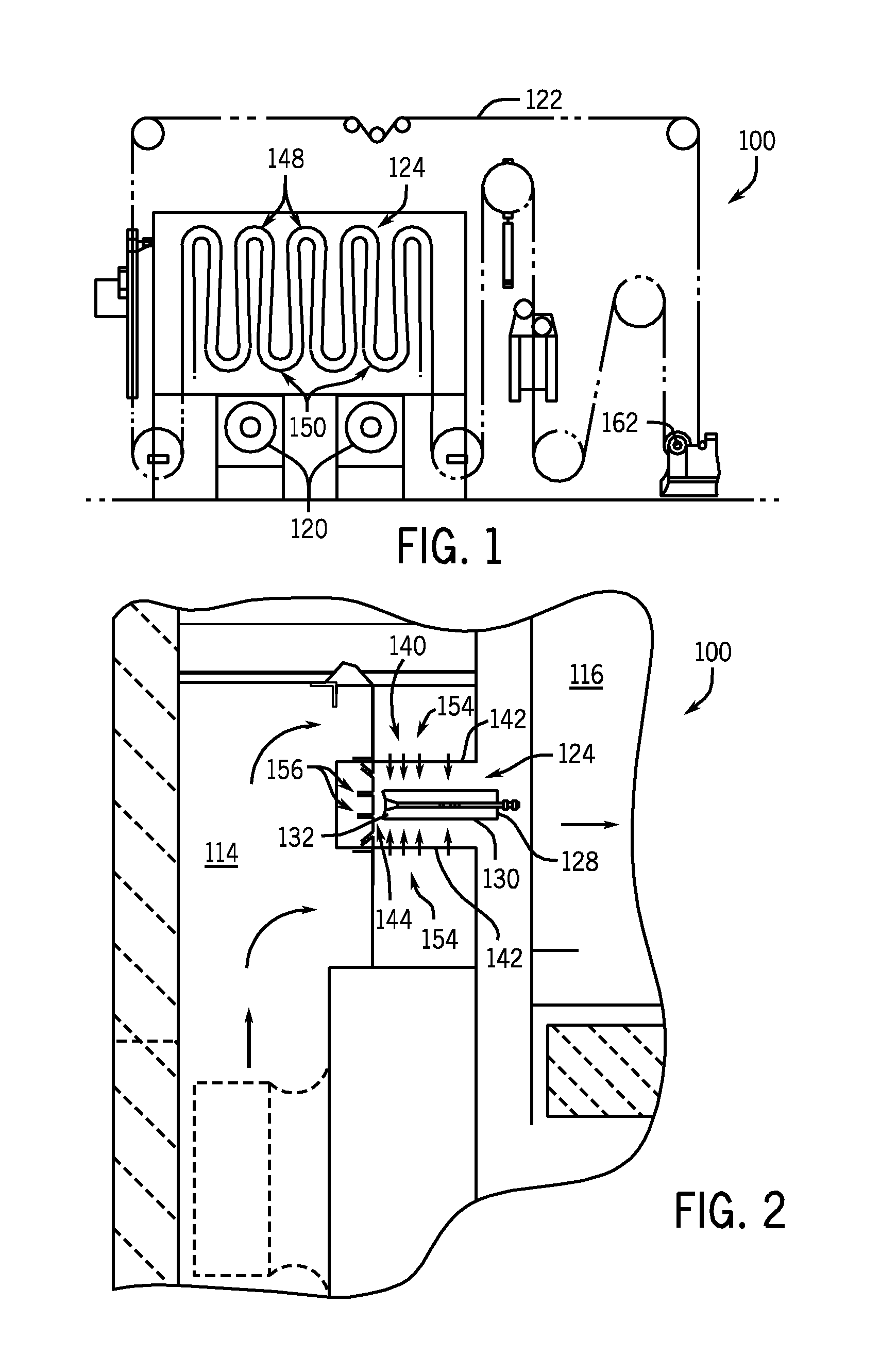
[0023]Referring to FIGS. 1-7, FIG. 1 is a schematic illustration of an exemplary embodiment of a pin oven 100 depicting a conveyor path 124 through the oven 100. A conveyor 122, for example a chain link conveyor is guided through the oven with a series of pulleys and sprockets and driven by a motor 162. A plurality of pins 126 are coupled to the conveyor 122 in a spaced-apart relationship and extending perpendicular from the chain into the oven 100. The chain also moves through other associated equipment (not shown) where containers 130, for example metal cans, are placed on each pin. Inks over varnish are applied to the containers 130 by the equipment outside of the oven 10 and the containers 130 are then moved into the oven for a drying process. The containers exit the oven 100 and move on for further processing.

[0024]FIG. 1 and FIG. 6 illustrate what is known as a ten-pass oven since the U-shaped duct path 124 through the oven consists of ten legs. It should be understood that ot...


PUM


Abstract

An oven configured for drying a container. The oven includes a housing defining an interior space including a supply chamber and a return chamber. A conveyor is configured for movement within a portion of the interior space of the housing defined by a plurality of semi-circular shaped duct sections connected at each end of the semi-circular shaped duct sections to a straight duct section. Each duct section includes two side walls coupled to a back wall defining a continuous U-shaped duct path through which the conveyor moves. The oven is further configured to provide a temperature difference between any two points within the interior space of the oven housing controlled to plus or minus two degrees Fahrenheit, by a uniform air flow throughout the oven. The uniform air flow is facilitated by the sizing and spacing of various circular orifices and slotted orifices in the continuous duct path.

Description

FIELD OF THE INVENTION[0001]The present invention pertains to ovens, more particularly, to pin ovens for drying open-ended cans.BACKGROUND OF THE INVENTION[0002]Pin ovens are well known in the art and are widely used in the food and beverage can manufacturing industry for drying the coatings on the exterior of partially completed, open-ended, steel and aluminum cans. The coating applied to the exterior of the cans may include an ink or enamel used to apply the label, an overcoat of lacquer or varnish, or both, a printed label and overcoat.[0003]A typical pin oven includes a conveyor chain mounted for movement in a generally vertical serpentine path defined by a series of straight runs connected by curved sections. Carrier pins are attached to the conveyor chain in spaced relation along its entire length substantially perpendicular to the chain conveyor. The open-ended cans are placed onto the extended pins and are carried over the serpentine path through the oven. Nozzles aligned wi...

Claims


Application Information

Patent Timeline
Patent Type & Authority Patents(United States)
IPC IPC(8): F26B3/04F26B15/10F26B21/00
CPCF26B3/04F26B15/10F26B21/004F26B15/12F26B15/18F26B2210/00
Inventor ZEA, JOHNZHAO, YOUGUIBEIN, DAN
Owner INT THERMAL SYST
Why Eureka
Try Eureka