
Solenoid valve

a solenoid valve and valve body technology, applied in the field of solenoid valves, can solve the problems of destabilization of controllability and decline of contamination resistan

Active Publication Date: 2015-02-24
EAGLE INDS
View PDF20 Cites 6 Cited by
  • Summary
  • Abstract
  • Description
  • Claims
  • Application Information

AI Technical Summary

Benefits of technology

This design achieves good control stability and excellent contamination resistance while allowing for easy adjustment of the maximum flow amount, ensuring smooth fluid flow and axial movement of the spool, thereby enhancing the overall performance of the solenoid valve.

Problems solved by technology

However, when the controlled flow amount is increased, there may be a risk to cause problems such that controllability is destabilized due to an increase in fluid force associated therewith and that contamination resistance is declined due to an increase in contamination amounts passing through the valve portion.

Method used


Image

  • Solenoid valve
  • Solenoid valve
  • Solenoid valve

Examples


example 1

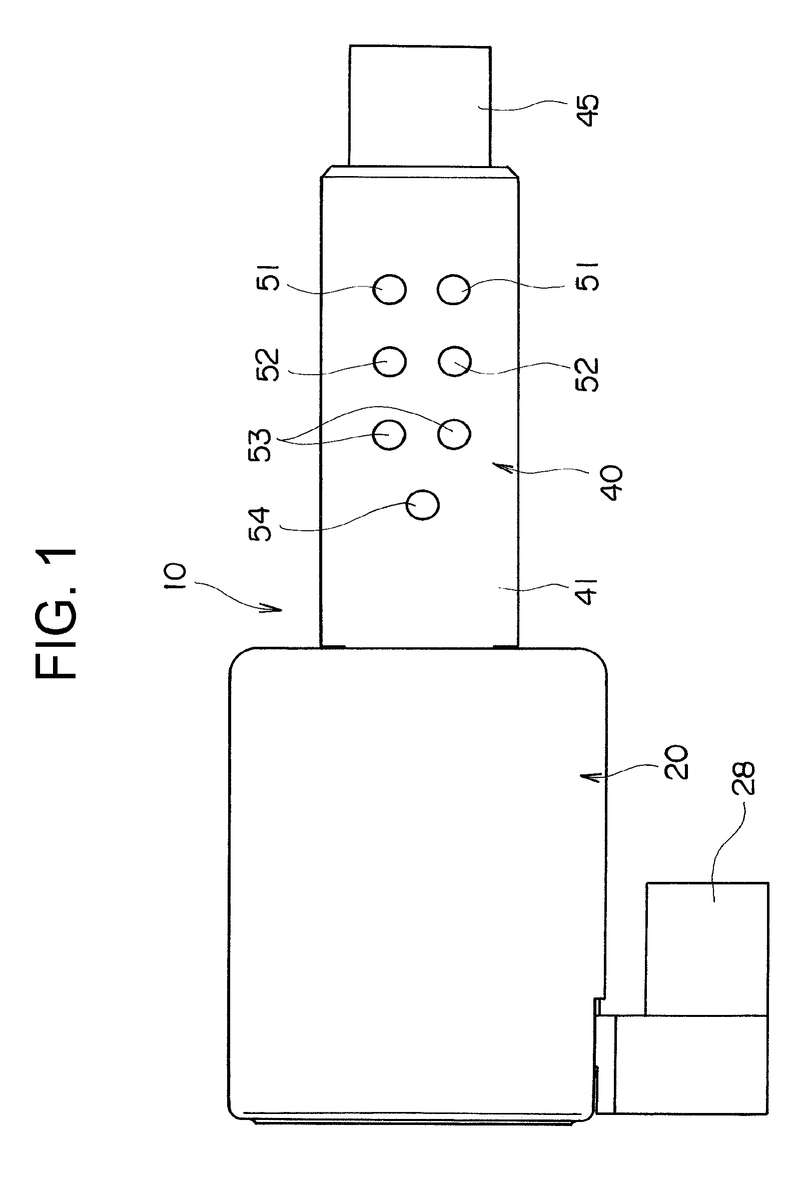
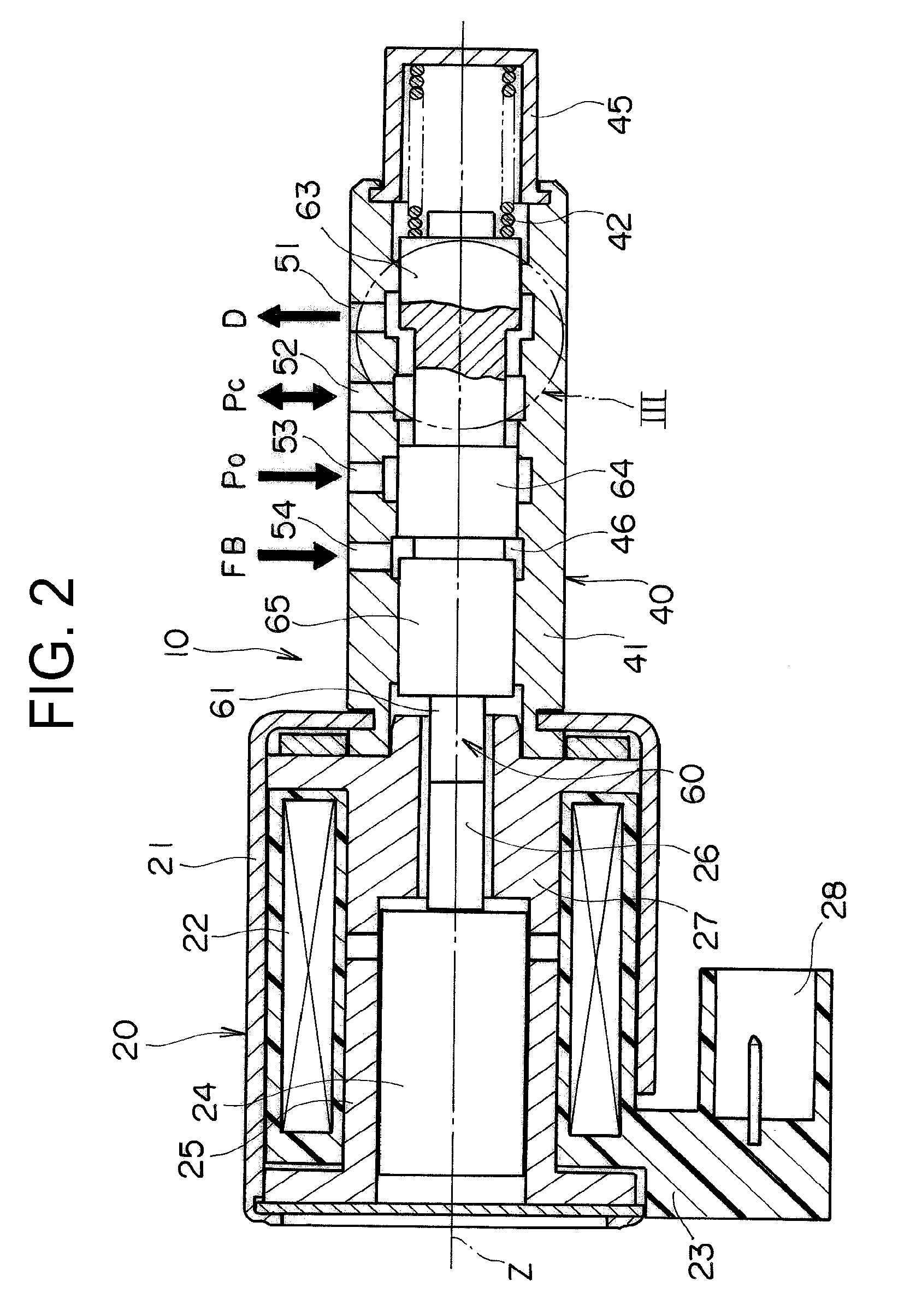
[0046]The input port 53 of the solenoid valve 10 shown in FIG. 1 to FIG. 4 was connected to a hydraulic pressure providing portion as a hydraulic system; the control port 52 was connected to an object (clutch) to be controlled; the outlet port 51 was connected to atmospheric pressure (external space); and the feedback port 54 was connected to the control port 52. The pressure Po at the input port was 2 MPa; the pressure Pc at the control port was 0 to 2 MPa; the pressure D at the outlet port was atmospheric pressure; and the pressure FB at the feedback port was 0 to 2 MPa.

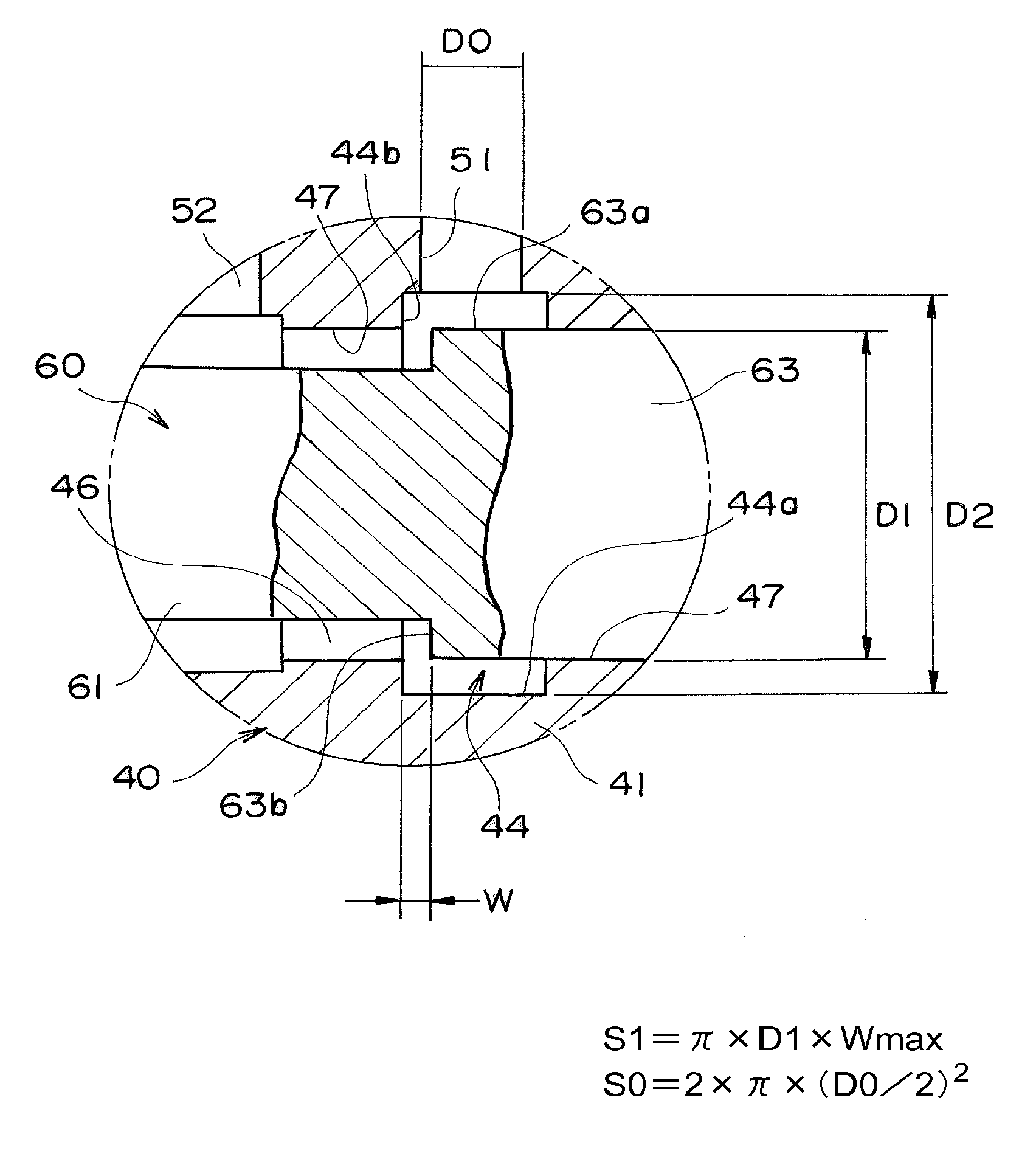
[0047]It was confirmed that S1 at the outlet port was 17.4 mm2; S0 was 8.3 mm2; and the relation of S1≧S0 was fulfilled. Also, it was confirmed that S1′ at the input port was 17.4 mm2; S0′ was 8.3 mm2; and the relation of S1′≧S0′ was fulfilled.


PUM


Abstract

A solenoid valve 10 including a valve sleeve 41, and a solenoid portion 20 which is mounted at one end along axial direction of the valve sleeve 41. A plurality of ports 51 to 54 are formed on the valve sleeve 41. In at least an outlet port 51 of the plurality of ports, a relation of S1≧S0 is fulfilled, where S1 is an opening area of valve portion when the spool 60 moves in an axial direction to maximally open the valve portion between the outlet port 51 and the internal flow passage 47, and S0 is the total flow passage cross-sectional area.

Description

CROSS-REFERENCE TO RELATED APPLICATIONS[0001]This application is a 371 U.S. National Stage of International Application No. PCT / JP2010 / 066194, filed Sep. 17, 2010, and claims priority to Japanese patent application No. 2009-270605, filed Nov. 27, 2009, the disclosures of which are herein incorporated by reference in their entirety.TECHNICAL FIELD[0002]The present invention relates to a solenoid valve preferable to be applied in hydraulic control of a hydraulic system, for example.BACKGROUND ART[0003]For example, in a spool-type solenoid valve for hydraulic control shown in JP 2007-285457, it is necessary to increase a controlled flow amount of the solenoid valve for improving response characteristics of controlled hydraulic pressure. Therefore, it has conventionally been dealt with by expanding a valve opening amount of a valve portion, and expanding a flow passage cross-sectional area of each port of a valve sleeve, which is another hydraulic pressure route.[0004]However, when the ...

Claims


Application Information

Patent Timeline
Patent Type & Authority Patents(United States)
IPC IPC(8): F16K31/06F15B13/04F16K11/07
CPCF16K31/0613F15B13/0402F16K11/07F16K27/048Y10T137/8671Y10T137/86614Y10T137/86622
Inventor NISHINOSONO, HIROYUKIKASAGI, YOSHINARI
Owner EAGLE INDS
Learn More