Sheet feeder with two suction wheels

a feeder and suction wheel technology, applied in the field of feeders, can solve the problems of mechanical limitation of the speed increase of the dragging suction unit, the dragging suction element cannot be carried, and the sheet cannot be transported during, so as to achieve high reliability, increase throughput, and low energy consumption.

Active Publication Date: 2015-02-24
HEIDELBERGER DRUCKMASCHINEN AG
View PDF17 Cites 0 Cited by
  • Summary
  • Abstract
  • Description
  • Claims
  • Application Information

AI Technical Summary

Benefits of technology

[0009]It is accordingly an object of the invention to provide a sheet feeder with two suction wheels which overcomes the hereinafore-mentioned disadvantages of the heretofore-known devices of this general type and which operates with high reliability independently of the quality of the sheet-shaped material to be processed and with increased throughput (i.e. an increased number of sheets fed per unit of time) in a cost-efficient way and at low energy consumption. A further object is to permit the feeding of shingled or overlapping sheets.
[0011]The sheet feeder of the invention is used to separate sheets of paper, board, plastic and the like from a stack and to feed the sheets in a direction of sheet travel and in a plane of sheet travel to a downstream machine for processing sheets such as a folder. The sheet feeder advantageously has a first suction wheel as viewed in the direction of sheet travel and a second suction wheel as viewed in the direction of sheet travel, the first suction wheel being disposed above the stack and the second suction wheel being disposed downstream of the stack as viewed in the direction of sheet travel and above or preferably below the plane of sheet travel. A configuration below the plane of sheet travel is preferred because it permits a shingled feeding of sheets. Each suction wheel is used to attract and transport the sheets by suction. Return movements causing dead time are no longer necessary. The use of rotating suction wheels that may be continuously operated may thus result in a significant increase of the throughput of the sheet feeder, i.e. in an accelerated operating cycle of the sheet feeder.
[0014]A first distance A between an axis of rotation of the first suction wheel and the rear edge of the stack is advantageously greater than or at least equal to a second distance B between an axis of rotation of the second suction wheel and the front edge of the stack with the distances A, B being measured in the horizontal. This ensures that a respective sheet may be gripped by the second suction wheel in the region of the leading edge of the sheet before the first suction wheel releases the sheet in the region of its trailing edge. A respective sheet may thus be transferred from the first suction wheel to the second suction wheel in a defined way and may thus be reliably transported.
[0016]In accordance with a further particularly advantageous and thus preferred feature of the sheet feeder of the invention, during operation of the sheet feeder the average rotational speed of the second suction wheel is higher than the average rotational speed of the first suction wheel, and the current rotational speed of the second suction wheel is always higher than the current rotational speed of the first suction wheel. This embodiment advantageously allows a respective sheet to be securely gripped and separated by the first suction wheel at a reduced speed and then to be accelerated by the second suction wheel up to the speed of the machine processing printing material that is disposed downstream of the sheet feeder. In a borderline case, the speeds of rotation are at least equal. For this purpose, a first drive may be provided for the first suction wheel and a second drive may be provided for the second suction wheel. For example, both drives may be servomotors. Alternatively, one electric motor may be provided and a gearing mechanism may be disposed between the electric motor and the respective suction wheel.
[0020]In accordance with yet a further development of this alternative, the sheet feeder has a machine control unit and a servomotor that is connected to the machine control unit by data lines and drives the first suction wheel. The servomotor is actuatable and is actuated in such a way that it imparts a rotary movement to the suction wheel only during the “holding the sheet” cycle. During the “attracting the sheet” and “releasing the sheet” cycles, the suction wheel does not rotate. Thus, any relative movement between the first suction wheel and the sheet is prevented when the sheet is being gripped and released, to avoid marking the sheet.
[0021]In accordance with yet an added development of an embodiment having a suction wheel that continuously exercises a suction effect, the sheet feeder has a drive that is connected to the first suction wheel for rotating the first suction wheel at a constant rotational speed. Since this alternative is much easier to control, it constitutes a particularly robust and stable configuration.

Problems solved by technology

A disadvantage of such alternating systems is that the dragging suction element carries out a reciprocating movement and can only transport a sheet during the advancing movement.
No sheet can be transported during the return movement, which is a resetting movement of the dragging suction element and represents dead time.
The speed increase of the dragging suction unit is mechanically limited due to the translatory, alternating sequence of motions.
An increased speed causes deformations and damage to a respective signature, which may result in transportation problems and a significant deterioration of the quality of the final products.

Method used


Image

  • Sheet feeder with two suction wheels
  • Sheet feeder with two suction wheels
  • Sheet feeder with two suction wheels

Examples


Embodiment Construction

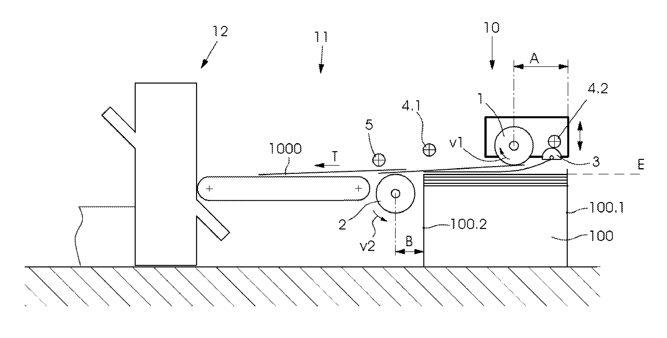
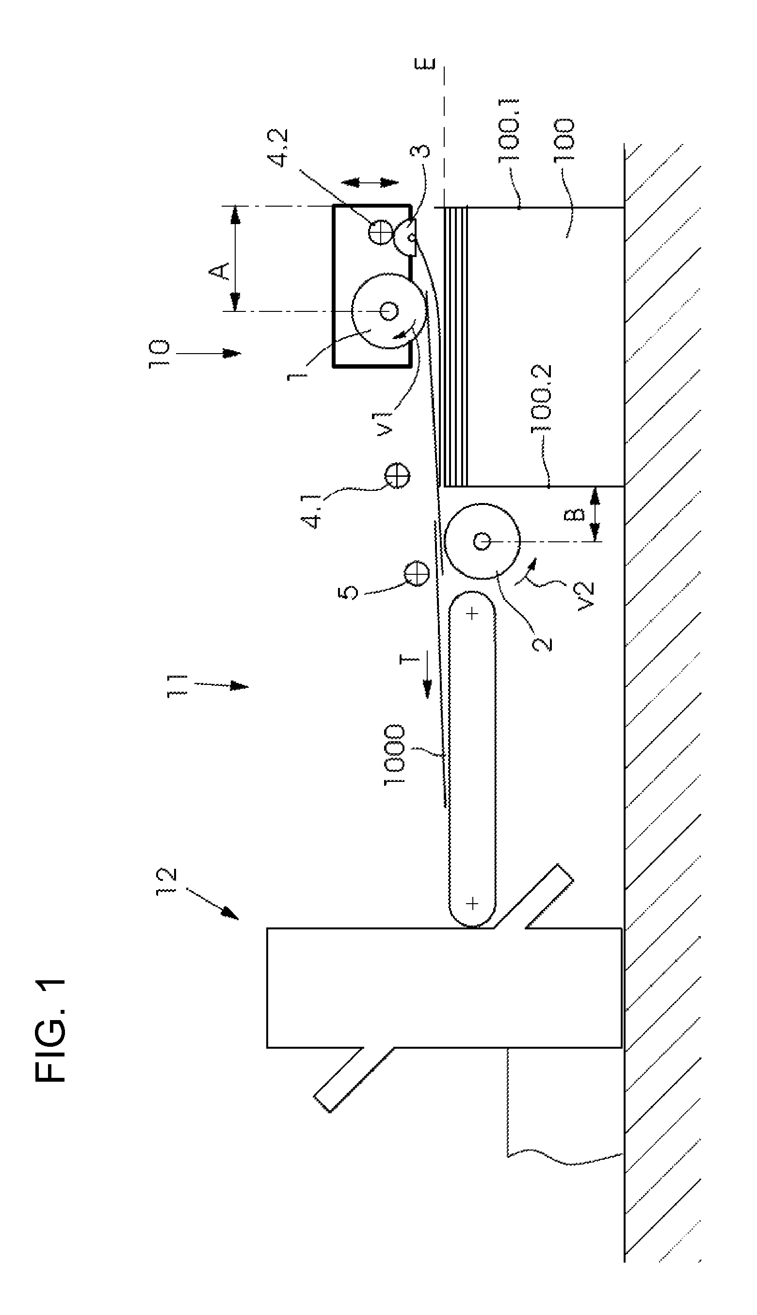
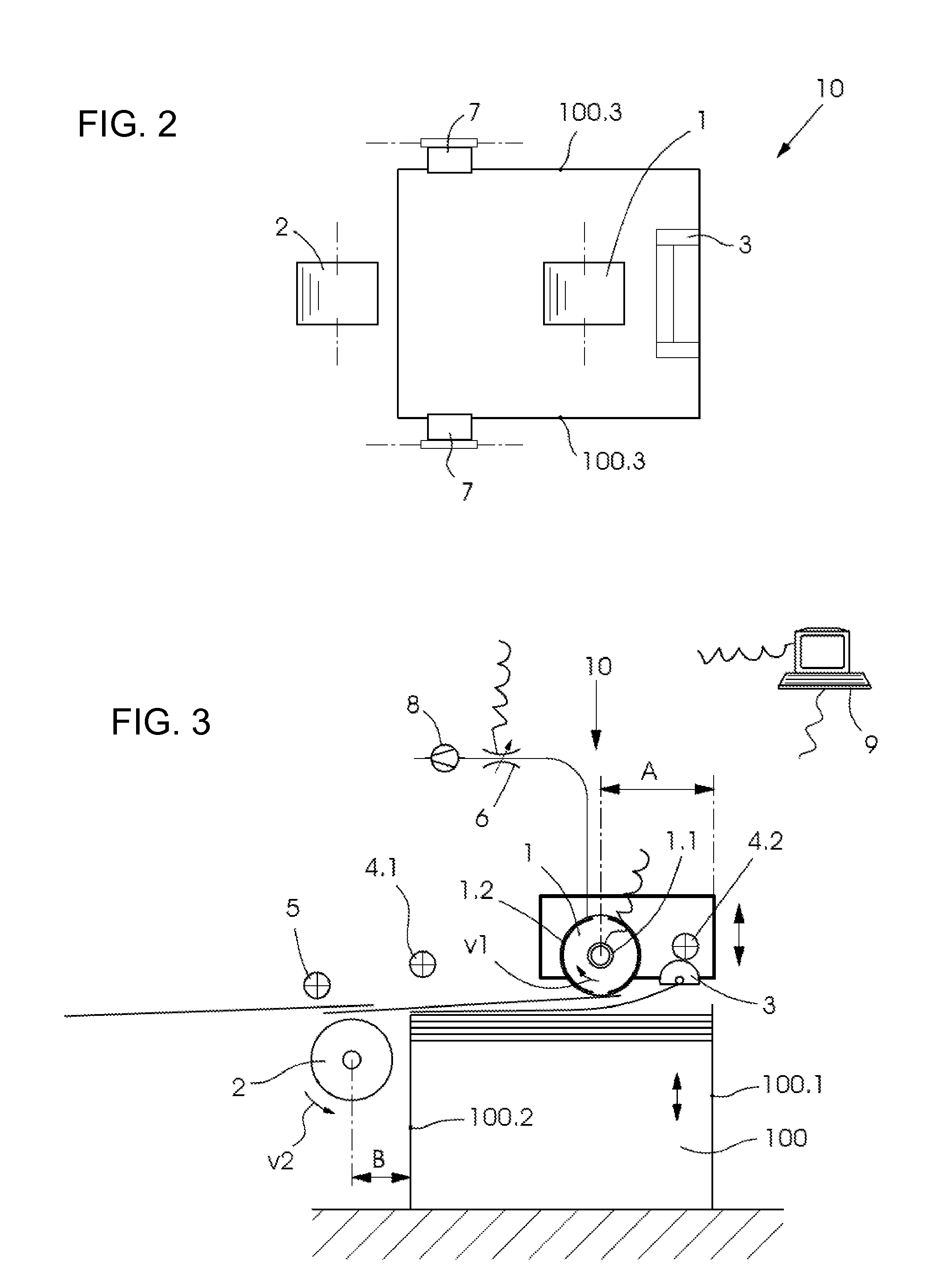
[0034]Referring now in detail to the figures of the drawings, in which like elements have like reference symbols, and first, particularly, to FIG. 1 thereof, there is seen a sheet feeder 10 of the invention for separating sheets 1000 from a stack 100 of sheets and for feeding the separated sheets 1000 over a feed table 11 to a machine 12 for processing sheets. The illustrated machine 12 for processing sheets is a buckle folding unit in a sheet-fed folder. The sheet feeder 10 includes a first suction wheel 1 and a second suction wheel 2. The first suction wheel 1 is disposed above the stack 100 of sheets. The second suction wheel 2 is disposed below a plane E of sheet travel and downstream of the stack 100 as viewed in a direction of sheet travel T. The axis of rotation of the first suction wheel 1 is at a first distance A from a rear edge 100.1 of the stack 100 of sheets. The second suction wheel 2 is disposed at a second distance B from a front edge 100.2 of the stack 100 of sheets...


PUM


Abstract

A sheet feeder for separating sheets from a stack and for feeding the sheets to a downstream sheet processing machine includes a first suction wheel and a second suction wheel. The first suction wheel is disposed above the stack and the second suction wheel is disposed downstream of the stack and below a sheet travel plane. The first suction wheel separates a respective sheet from the stack and the second suction wheel accelerates the sheet.

Description

CROSS-REFERENCE TO RELATED APPLICATION[0001]This application claims the priority, under 35 U.S.C. §119, of German Patent Application DE 10 2011 120 475.3, filed Dec. 8, 2011; the prior application is herewith incorporated by reference in its entirety.BACKGROUND OF THE INVENTION[0002]1. Field of the Invention[0003]The invention relates to a sheet feeder for separating sheets of paper, cardboard, plastic and the like from a stack and for feeding the sheets in a sheet travel direction in a sheet travel plane to a downstream sheet processing machine. The sheet feeder includes a first suction wheel as viewed in the sheet travel direction and a second suction wheel as viewed in the sheet travel direction. The first suction wheel is disposed above the stack and the second suction wheel is disposed downstream of the stack and above or below the sheet travel plane.[0004]2. Description of the Related Art[0005]Buckle folders are known in the art. The structure of a buckle folder including a pl...

Claims


Application Information

Patent Timeline
Patent Type & Authority Patents(United States)
IPC IPC(8): B65H3/40B65H3/08B65H3/10B65H5/12B65H5/22
CPCB65H5/12B65H3/0825B65H3/10B65H5/226B65H2406/33B65H2511/22B65H2801/24
Inventor HAUPT-TERLAU, MARTIN
Owner HEIDELBERGER DRUCKMASCHINEN AG
Why Eureka
Try Eureka