White organic light emitting device

a light emitting device and organic technology, applied in the direction of electroluminescent light sources, thermoelectric devices, electric lighting sources, etc., can solve the problems of difficult multiple use limited components of the dopant included in the corresponding light emitting layer, and sag may occur due to the load of the shadow mask, so as to improve the efficiency of blue light emitting and improve the efficiency of white display. , the effect of improving the lifespan

Active Publication Date: 2015-02-24
LG DISPLAY CO LTD
View PDF15 Cites 126 Cited by
  • Summary
  • Abstract
  • Description
  • Claims
  • Application Information

AI Technical Summary

Benefits of technology

[0018]An object of the present invention is to provide a white organic light emitting device having a dual stack structure, in which an electron transport layer adjacent to a blue light emitting layer includes an electron transport catalyst layer including metal to improve blue light emitting efficiency, and a greenish yellow dopant is used to improve white display efficiency, increase lifespan, and reduce power consumption.

Problems solved by technology

However, in case of a shadow mask having a large area, sag may occur due to load of the shadow mask.
For this reason, it is difficult to use the shadow mask several times, and a defect occurs in forming a pattern of the organic light emitting layer.
However, a problem occurs in that there is a limitation in components of the dopant included in the corresponding light emitting layer due to properties of the dopant.
Also, a problem occurs in that a color shift occurs due to the difference in lifespan among the dopants when the dopants continue to be used.
Moreover, as similar energy levels occur in the boundary between a light emitting layer and a hole transport layer, a problem occurs in that a triplet exciton moves to the hole transport layer over the boundary and thus light emitting efficiency of excited state is deteriorated.
This could lead to many problems in obtaining a white organic light emitting device having proper efficiency.
For this reason, a white organic light emitting device having a blue fluorescent layer has been mainly developed but is restrictive due to efficiency problem in view of color temperature, lifespan and power consumption.

Method used


Image

  • White organic light emitting device
  • White organic light emitting device
  • White organic light emitting device

Examples


Embodiment Construction

[0042]Reference will now be made in detail to the preferred embodiments of the present invention, examples of which are illustrated in the accompanying drawings. Wherever possible, the same reference numbers will be used throughout the drawings to refer to the same or like parts.

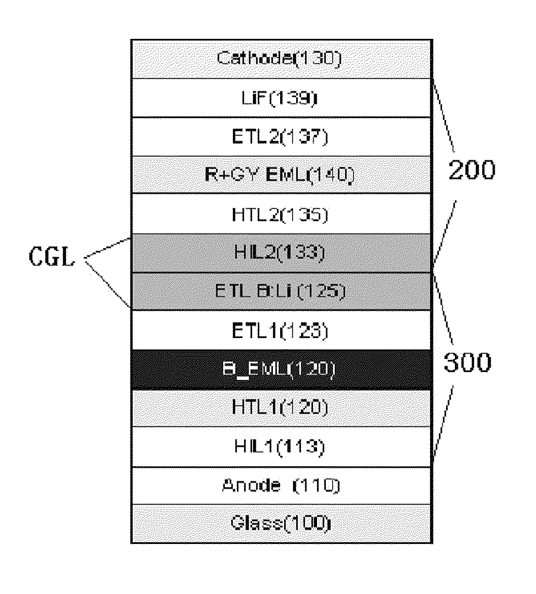
[0043]When a white organic light emitting device has a two-stack structure, each of the first stack and the second stack includes a blue light emitting layer and red and green light emitting layers. In this case, the stack structure includes two types of structures. One type is that all the light emitting layers are formed in a fluorescent structure, and the other type is that a blue light emitting layer is formed in a fluorescent structure and red and green light emitting layers are formed in a phosphor structure.

[0044]In case of the first type, a problem occurs in that light emitting efficiency is low in view of properties of fluorescent material. In case of the second type, a problem occurs in that lifesp...


PUM


Abstract

A white organic light emitting device having a dual stack structure is disclosed, in which an electron transport layer adjacent to a blue light emitting layer includes an electron transport catalyst layer including metal to improve blue light emitting efficiency, and a greenish yellow dopant is used to improve white display efficiency, increase lifespan, and reduce power consumption.

Description

[0001]This application claims the benefit of the Patent Korean Application No. 10-2009-0113752, filed on Nov. 24, 2009, which is hereby incorporated by reference as if fully set forth herein.BACKGROUND OF THE INVENTION[0002]1. Field of the Invention[0003]The present invention relates to an organic light emitting device, and more particularly, to a white organic light emitting device having a dual stack structure, in which an electron transport layer adjacent to a blue light emitting layer includes an electron transport catalyst layer including metal to improve blue light emitting efficiency, and a greenish yellow dopant is used to improve white display efficiency, increase lifespan, and reduce power consumption.[0004]2. Discussion of the Related Art[0005]Recently, with the advent of the age of information, a display field that visually displays an electrical information signal has been rapidly developed. In this respect, various flat display devices having excellent performance such...

Claims


Application Information

Patent Timeline
Patent Type & Authority Patents(United States)
IPC IPC(8): H01L29/08H01L51/50
CPCH01L51/5036H01L51/5016H01L51/5048H10K50/125H10K50/14H10K50/11H10K2101/10H05B33/14H05B33/18H10K50/00
Inventor PIEH, SUNG-HOONKIM, CHANG-OH
Owner LG DISPLAY CO LTD
Why Eureka
Try Eureka