Wavelength sweeping light source and imaging apparatus using the same

a light source and wavelength technology, applied in the direction of optical resonator shape and construction, semiconductor lasers, instruments, etc., can solve the problems of laser apparatus, insufficient broadening of the dispersion of the resonator, and limited sweep rang

Inactive Publication Date: 2015-02-24
CANON KK
View PDF10 Cites 0 Cited by
  • Summary
  • Abstract
  • Description
  • Claims
  • Application Information

AI Technical Summary

Benefits of technology

[0021]The present invention relates to a light source apparatus that can realize a high-speed and broad-band wavelength sweeping operation.
[0023]The light source apparatus according to the present invention includes a plurality of second optical resonators connected in parallel to the laser oscillator equipped with the first optical resonator. Both the optical member having refractive index dispersion and the optical amplification member are provided in each second optical resonator. The light multiplexing unit multiplexes a plurality of light beams extracted from the plurality of second optical resonators and outputs a multiplexed light beam. The optical amplification media of respective second optical resonators are different from each other in maximum gain wavelength. Multiplexing the plurality of light beams extracted from the plurality of second optical resonators and outputting a multiplexed light beam can realize a broad-band wavelength sweeping operation. Further, using the optical member having refractive index dispersion can realize a high-speed wavelength sweeping operation based on the dispersion tuning.

Problems solved by technology

Therefore, the sweep range is limited by the wavelength dispersion in the resonator cannot be sufficiently broadened.
However, the laser apparatus discussed in PTL 1 does not perform any operation for sweeping the wavelength of the output light.

Method used


Image

  • Wavelength sweeping light source and imaging apparatus using the same
  • Wavelength sweeping light source and imaging apparatus using the same
  • Wavelength sweeping light source and imaging apparatus using the same

Examples


Embodiment Construction

[0043]Various exemplary embodiments, features, and aspects of the invention will be described in detail below with reference to the drawings.

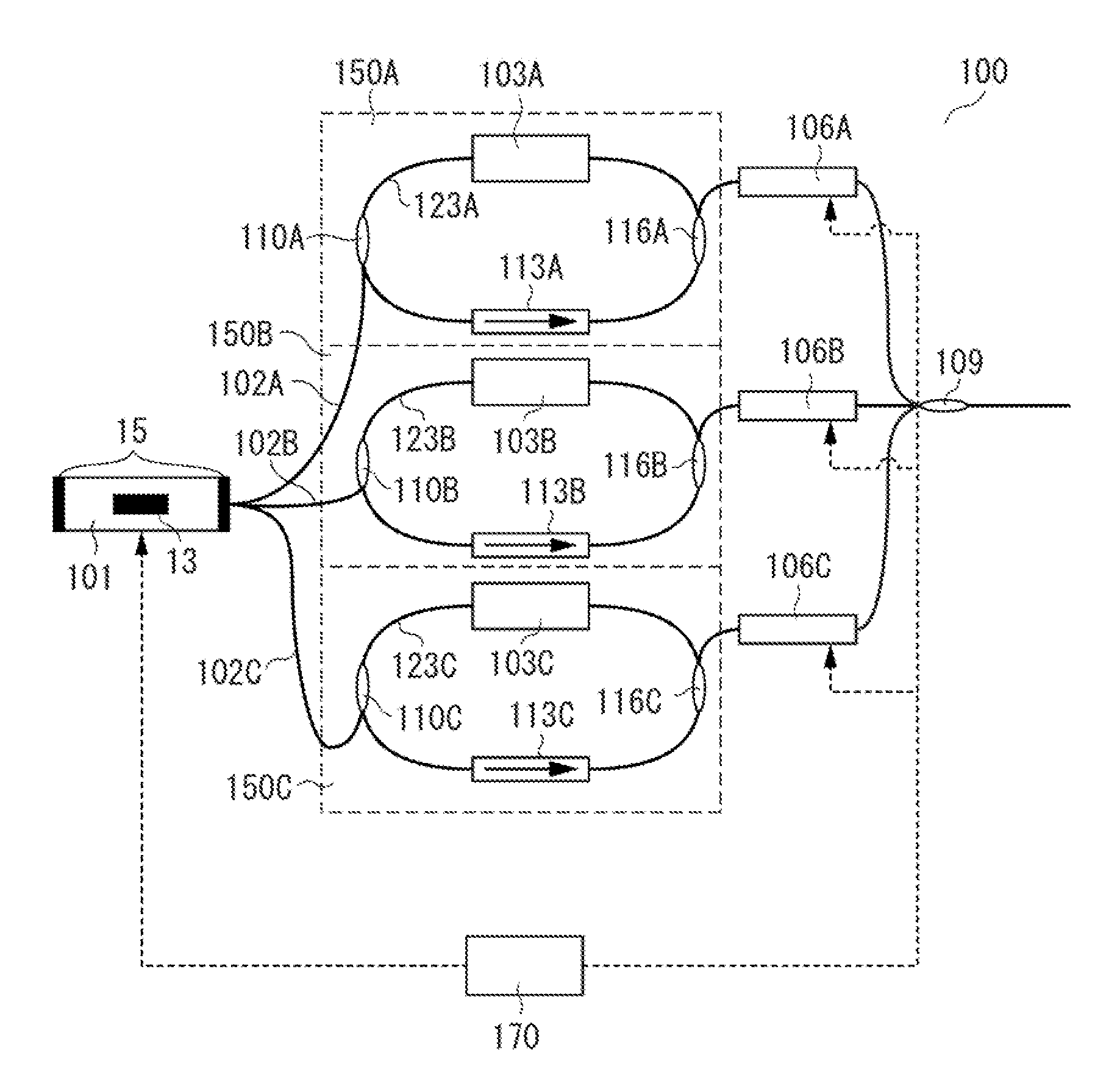
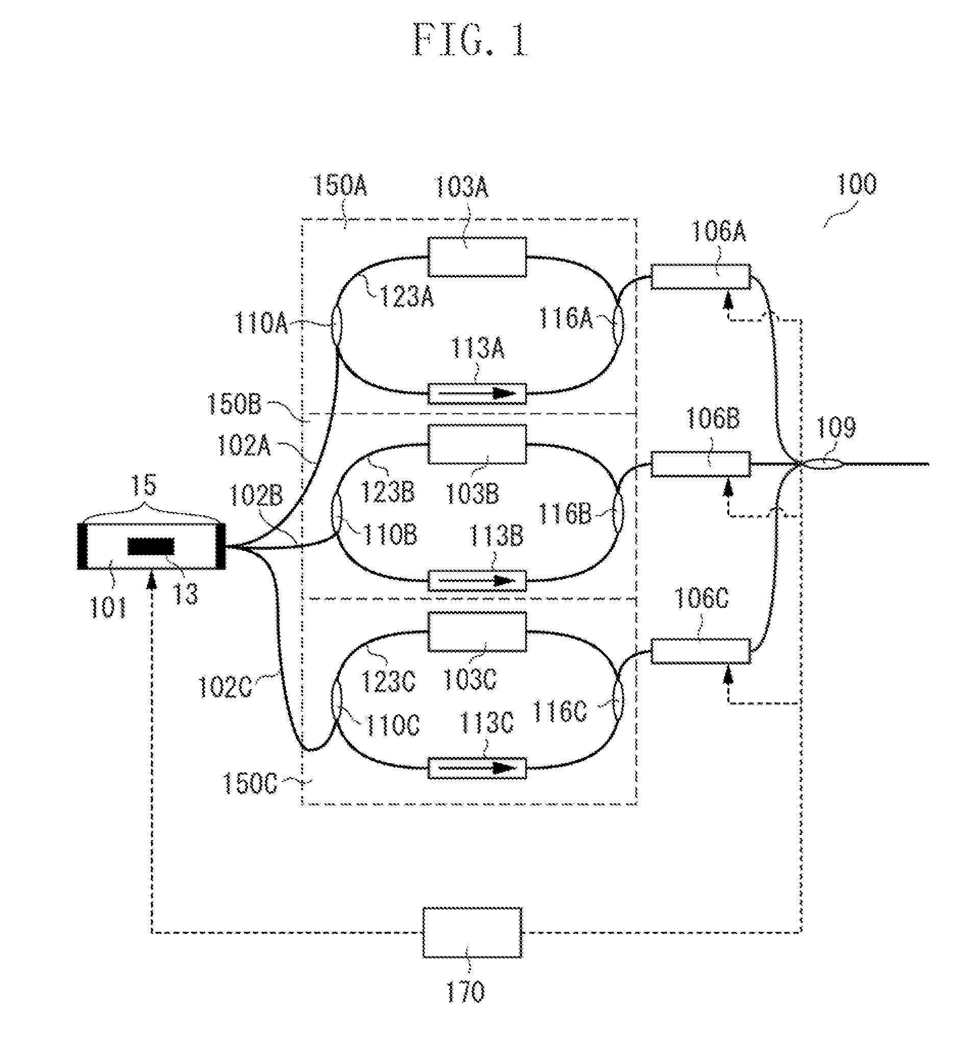
[0044]FIG. 1 illustrates a schematic example of a light source apparatus according to the present invention.

[0045]A light source apparatus 100 illustrated in FIG. 1 includes a laser oscillator 101 equipped with a first optical resonator 15, and a plurality of second optical resonators 150A, 150B, and 150C respectively having input portions 110A, 110B, and 110C connected in parallel to the first optical resonator 15. The light source apparatus 100 further includes light extraction units 106A, 106B, and 106C that can extract light beams from output portions 116A, 116B, and 116C of respective second optical resonators 150A, 150B, and 150C, and a light multiplexing unit 109 that can multiplex a plurality of light beams extracted from the light extraction units 106A, 106B, and 106C.

[0046]The laser oscillator 101 includes an optical amplification med...


PUM


Abstract

A light source apparatus includes a laser oscillator equipped with a first optical resonator, a plurality of second optical resonators including input portions respectively connected in parallel to the first optical resonator, a plurality of light extraction units configured to extract a light beam from an output portion of each second optical resonator, and a light multiplexing unit configured to multiplex the light beam extracted from each light extraction unit, wherein the light source apparatus causes the light multiplexing unit to output a multiplexed light beam passed through the plurality of second optical resonators, an optical member having refractive index dispersion and an optical amplification medium are disposed in each of the plurality of second optical resonators, and the optical amplification media of the plurality of second optical resonators are different from each other in maximum gain wavelength.

Description

BACKGROUND OF THE INVENTION[0001]1. Field of the Invention[0002]The present invention relates to a light source apparatus capable of changing an oscillation wavelength thereof and also relates to an imaging apparatus equipped with the light source apparatus.[0003]2. Description of the Related Art[0004]In the field of communication networks as well as in the field of inspection apparatuses, a light source apparatus capable of changing an oscillation wavelength is well known. Recent developments in these fields have raised the need to increase a wavelength sweep rate and widen a sweep band of the light source apparatus.[0005]As an example of an inspection apparatus, there is an optical coherence tomography (OCT) apparatus configured to capture a tomographic image of an inspection target based on optical coherence. OCT is a non-invasive imaging technique, which can be widely practiced in the medical field because of its noninvasiveness. Recently, a new technique for OCT, known as swept...

Claims


Application Information

Patent Timeline
Patent Type & Authority Patents(United States)
IPC IPC(8): H01S3/10G01B9/02H01S3/08H01S3/083H01S5/00H01S5/065H01S5/0683H01S5/14H01S5/40
CPCG01B9/02007H01S5/0656H01S5/14G01B9/02004G01B9/02027G01B9/02091H01S3/08013H01S3/083H01S3/10046H01S5/0085H01S5/0657H01S5/06835H01S5/4012H01S5/4087
Inventor YAMADA, TOMOHIROFURUSAWA, KENTARO
Owner CANON KK
Why Eureka
Try Eureka