Hybrid three-phase power flow analysis method for ungrounded distribution systems

a technology of power flow analysis and ungrounded distribution system, which is applied in the direction of electric controllers, ignition automatic control, instruments, etc., can solve the problems of all methods having their own limitations, and achieve the effects of simplifying the specific analysis of each type of system, fast and accurate, and improving computation efficiency

Inactive Publication Date: 2015-02-24
MITSUBISHI ELECTRIC RES LAB INC
View PDF21 Cites 3 Cited by
  • Summary
  • Abstract
  • Description
  • Claims
  • Application Information

AI Technical Summary

Benefits of technology

[0008]The objective of various embodiments of invention is providing a fast and accurate method for power flow analysis suitable for large-scale ungrounded distribution systems. The embodiments of the invention are based on a realization that partitioning the power distribution system according to its topology simplifies specific analysis of each type of system. This is because such partitioning can take advantage of matrix based methods for handling the multiple PV buses, and the computation efficiency provided by topology based method for radial systems. Thus, such partitioning and recursive analysis allows increasing efficiency of the power flow analysis.
[0010]In some embodiments, impacts of zero-impedance branches such as voltage regulators have been modeled by merging those branches with adjacent impedance branches, and the inaccuracy or divergence problem introduced by adding small impedance into those branches that used by conventional methods have been avoided. Unlike common practice to set active power for each phase arbitrarily, the method models the control requirements for three-phase PV buses with balanced voltages precisely, that is maintaining the sum of three phase active power constant, and maintaining three phase voltages balanced and with constant magnitudes. Besides the improvement of accuracy, the method also further reduce the admittance matrix by merging three phases of PV buses into one phase, and removing one of zero-impedance branch buses from the model.
[0011]Instead of setting the bus initial voltages with swing bus values, and initializing loop compensation currents as zeros, some embodiments initialize the bus voltages and loop compensation currents appropriately and, thus, further reduce the number of iterations for converged voltage and loop compensation solutions. For example, the initial loop compensation currents can be based on the connected loop loads and an allocation factor matrix defined solely by the loop path impedances. The initial bus voltages can be set based on amplifier factors of transformers and regulators along paths connecting each bus with the swing bus.

Problems solved by technology

All of those methods have their own limitations when applied to large systems either in modeling capabilities or computational efficiency.

Method used


Image

  • Hybrid three-phase power flow analysis method for ungrounded distribution systems
  • Hybrid three-phase power flow analysis method for ungrounded distribution systems
  • Hybrid three-phase power flow analysis method for ungrounded distribution systems

Examples


example

[0125

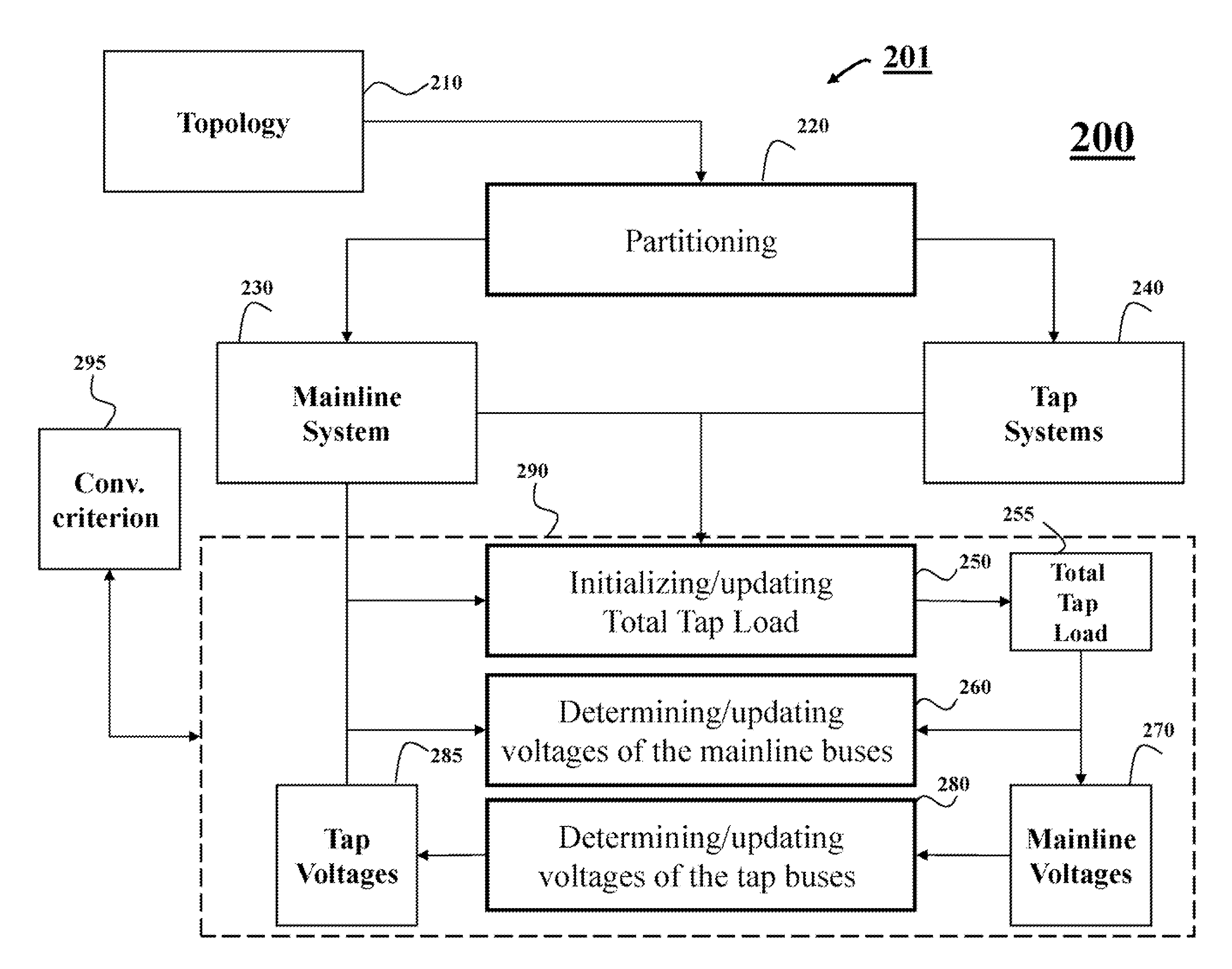
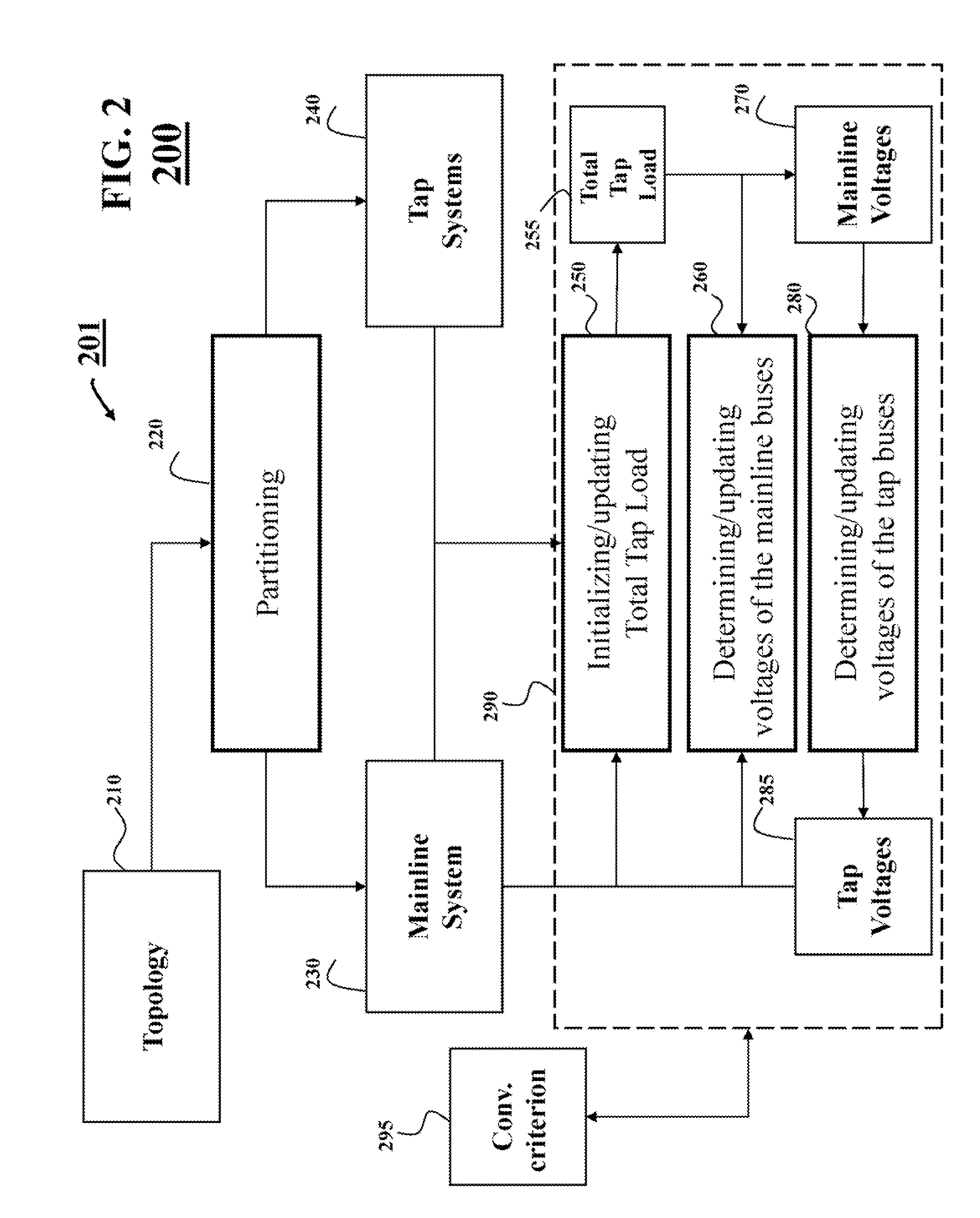
[0126]FIG. 9 shows a block diagram of a method 900 for analyzing a model of an ungrounded power distribution system according to one embodiment of the invention. Various embodiments of invention use at least part of the steps of the method 900.

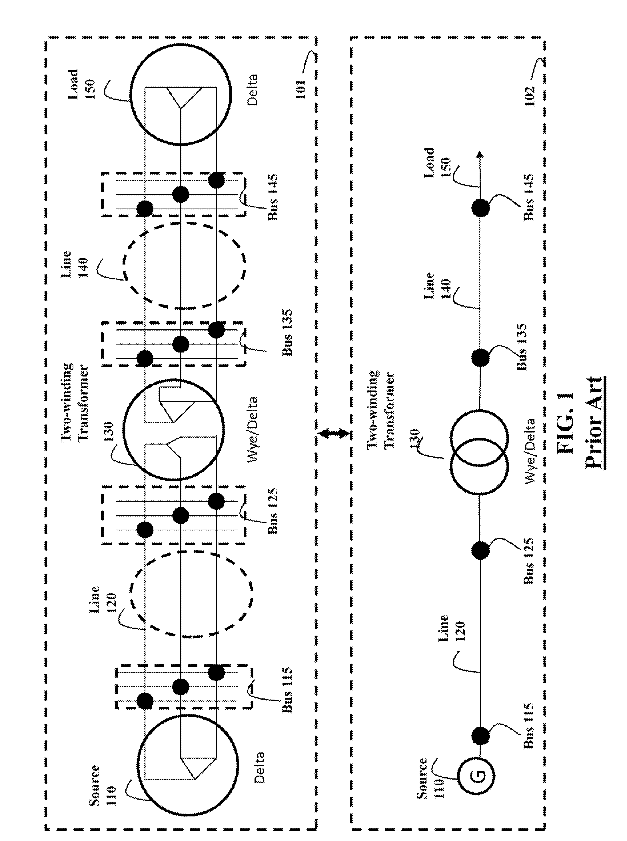
[0127]In step 910, three winding transformers are converted into three two-winding transformers to be modeled as shown in FIG. 4. After the conversion, the topology model of the system only contains two-terminal paths.

[0128]In step 915, the topology of the power distribution system is traced from the swing bus, and partition the system into mainline system and tap systems. The mainline system is constructed from all available paths between the swing bus and PV buses as shown in FIG. 3. The mainline system is a meshed system, if there is multiple paths between any pair of swing bus and PV bus existing. A tap system is constructed from one mainline bus and all downstream laterals connected with the bus. Depended on the distance from the bus...


PUM


Abstract

A method for a three phase power flow analysis of an ungrounded power distribution system partitions a topology of the power distribution system into a mainline system and a set of tap systems, wherein the mainline system is formed by mainline buses connecting a swing bus and a set of constant active power and voltage magnitude (PV) buses, wherein the tap system is formed by one or many tap buses, such that a root bus of each tap system corresponds to a mainline bus. Next, the method determines voltages of the mainline buses based on a function of a total load of each tap system; and determines voltages of tap buses based on a voltage of the corresponding root bus of the mainline and load of each tap bus.

Description

FIELD OF THE INVENTION[0001]This invention relates generally to power distribution systems, and more particularly to three-phase power flow analysis for ungrounded power distribution systems.BACKGROUND OF THE INVENTION[0002]The function of power distribution systems is delivering the electric powers from the transmission systems to the customers. The distribution system may be either a 3-phase 4 wire system, or a 3-phase 3 wire system. The power from transmission system or distribution generators are delivered to the customers through transmission lines, and various voltage regulating devices, such as voltage regulators, two-winding or three-winding transformers. The customer loads may be of single phase, or three-phase. The loads may be constant power load, constant current load or constant impedance load.[0003]FIG. 1 shows schematic diagrams of a sample distribution system including both the three-phase representation 101 and one-line diagram 102. The sample system includes one De...

Claims


Application Information

Patent Timeline
Patent Type & Authority Patents(United States)
IPC IPC(8): G05D3/12G05D17/00G05D11/00G05D9/00G05D5/00
CPCH02J3/06H02J2203/20Y02E60/00Y04S40/20Y04S20/222Y02B70/3225
Inventor SUN, HONGBO
Owner MITSUBISHI ELECTRIC RES LAB INC
Why Eureka
Try Eureka