Intrusion warning system

a warning system and intrusion technology, applied in the direction of optical radiation measurement, distance measurement, instruments, etc., can solve the problems of limited screening capabilities, limited widespread deployment, and high false alarm ra

Inactive Publication Date: 2015-03-03
SHILAT OPTRONICS
View PDF19 Cites 9 Cited by
  • Summary
  • Abstract
  • Description
  • Claims
  • Application Information

AI Technical Summary

Benefits of technology

[0005]The present disclosure describes new systems for the detection of intrusions over a line to be safeguarded, which combine low capital cost and high sensitivity with a low false alarm rate (FAR). The systems are based on the generation of an array of light beams projected into a two dimensional surface located generally along the line to be secured, and the detection of the distance and height of any spurious reflection from this array of light beams, by means of a detection array, detecting imaged fields of view within the surface along the line to be secured. The surface is most conveniently a plane surface, and will be so addressed henceforth, though this is not intended to limit the described systems to such planar surfaces. Such spurious reflections are assumed to arise from an intrusion object within the plane surveilled. Since the background reflection pattern without any intrusion can be acquired and stored by the system, a change in this detected background pattern can be defined as arising from a spurious reflection, and hence indicative of an intrusion. The angular direction from which the spurious reflection originates is known from the knowledge of which particular detector pixel has detected the spurious reflection signal, since each pixel may generally be directed to monitor a different field of view. The longitudinal position along the line of detection from which the spurious reflection is generated is known, if the particular beam which resulted in that reflection is also known. If the differently oriented beams are identifiable from each other in some way, then the illumination beam which caused the reflection detected can be determined, thus defining the position of the spurious reflection within the plane at the crossing point of the beam direction and the direction of that field of view in which a change in the reflected illumination beam is detected. The beams can be identified by projecting them sequentially according to a predetermined timed sequence, and relating the time of detection at the pixel to that predetermined timed sequence, such that the particular transmitting beam which generated the spurious reflection is known. This is a form of time division multiplexing whereby each light beam illuminates the area in a separate, known time interval. Alternatively, all of the beams can be activated at the same time, each beam having an identifiable modulation applied to it. The detection circuits are adapted to identify the beam by demodulating the signal detected, and identifying the location of the beam associated with that particular modulation. Alternatively, the beams can be distinguished by providing each with a different wavelength, or a different polarization type or orientation, and determining these characteristics to define the particular beam being detected. Any other devised form of beam identification may also be used without limiting the generality of the method.

Problems solved by technology

Current solutions based on video camera imaging, and using signal processing to detect changes in those images, generally have a number of disadvantages which have limited their widespread deployment, especially for border use over long distances, or in regions where the terrain is rough.
Such video systems may have high false alarm rates (FAR), limited capabilities for screening irrelevant intrusions such as by animals, significant power consumption, and they could be costly in capital expenses.

Method used


Image

  • Intrusion warning system
  • Intrusion warning system
  • Intrusion warning system

Examples


Embodiment Construction

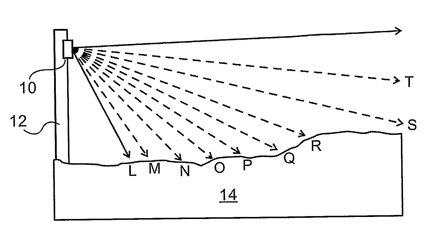
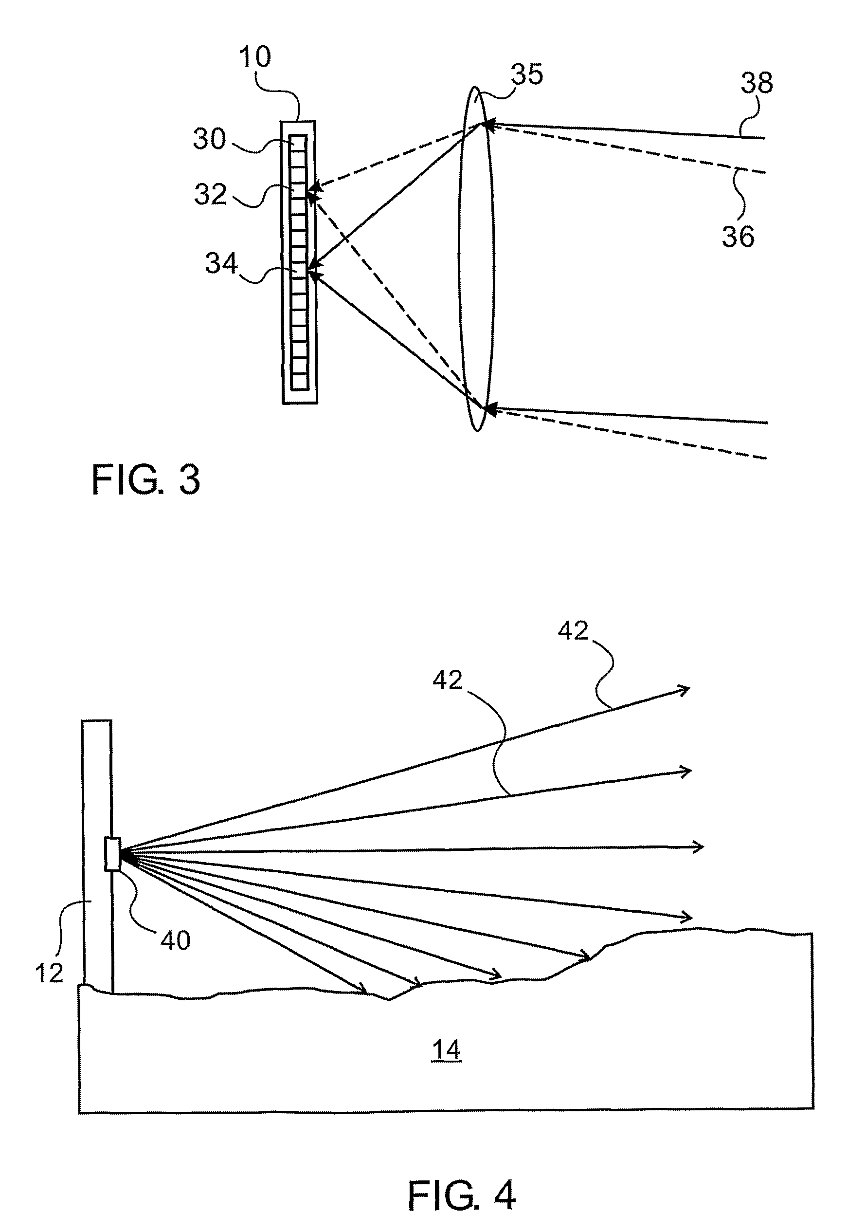
[0076]Reference is now made to FIG. 1, which illustrates schematically a side view of the terrain 14 covering configuration of a linear sensor of the type used in the presently described system. The sensor 10 may be suitably mounted on stakes or poles 12, and is positioned such that it looks along the line or border to be secured against intrusion. These stakes can either be support stakes of a real fence, in which case they detect the approach of an intruder at the fence, or they can be simply stakes positioned at regular intervals along the line to be secured, without any intervening physical fence, in which case they constitute a virtual fence. The linear sensor may be mounted essentially vertically, and individual pixels of the sensor are adapted to image different angular field of view directions of the area in front of the sensor, such as by, means of an imaging lens, as will be shown in FIG. 3 below. Each of these different angular directions therefore covers a different zone...


PUM


Abstract

A system for detecting intrusion across a surface, comprising a plurality of light sources projecting an array of illuminating beams along different optical paths in the surface and a detector array system directed such that it detects along a plurality of fields of view in the surface, illumination reflected from the illuminating beams. A signal processing system detects changes along the array of fields of view, in the reflected illumination level detected by the detector system. An increase greater than a predefined level in the reflected illumination level from any field of view provides an indication of an intrusion across the surveilled surface along that field of view, at the crossing point of the direction of that field of view with the optical path whose illuminating beam generated the increase in reflected illumination from that field of view.

Description

[0001]This is a 35 U.S.C. §371 application of PCT / IL2009 / 000417, filed Apr. 16, 2009, and claims the benefit under 35 U.S.C. §120 of said PCT application, and further claims the benefit under 35 U.S.C. §119(e) of U.S. Provisional Patent Applications U.S. Ser. No. 61 / 124,315, filed Apr. 17, 2008 and U.S. Ser. No. 61 / 202,689, filed Mar. 27, 2009. The contents of these priority applications are incorporated herein by reference.[0002]The present invention relates to the field of the surveillance of perimeter fences to protect against unauthorized intrusion, especially using optical techniques.BACKGROUND OF THE INVENTION[0003]Virtual fencing may be used for protecting or securing a separation line against intrusion by unwanted persons or objects in applications where a physical fence is inadequate or impractical, such as over long distances or where the terrain is too rough, or the cost is too high. The virtual fence could be used to protect a border, or the perimeters of an enclosed sec...

Claims


Application Information

Patent Timeline
Patent Type & Authority Patents(United States)
IPC IPC(8): G08B13/18G01C3/08G01S17/04
CPCG08B13/181G08B13/2491G01S17/04
Inventor GUETTA, AVISHAYKORNGUT, DORONBLAI, GIL
Owner SHILAT OPTRONICS
Why Eureka
Try Eureka