
Radar apparatus and method

a technology of radar apparatus and antenna, which is applied in the field of radar apparatus, can solve the problems of poor range resolution and the inability of the technique to achieve the theoretical range resolution, and achieve the effect of improving the range resolution without increasing the bandwidth and being easy to apply

Inactive Publication Date: 2015-03-03
SONY CORP
View PDF6 Cites 14 Cited by
  • Summary
  • Abstract
  • Description
  • Claims
  • Application Information

AI Technical Summary

Benefits of technology

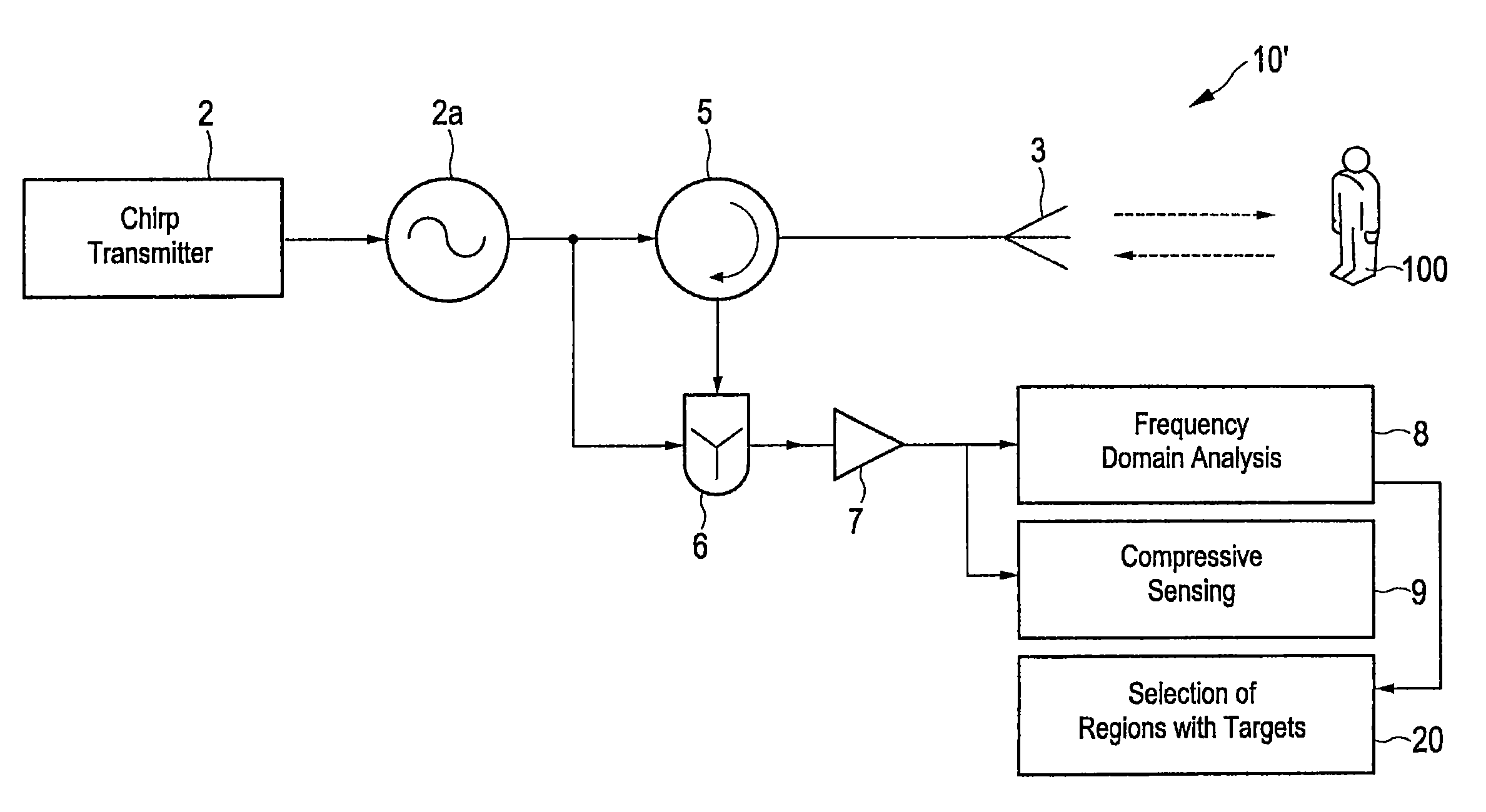
This patent is about a way to make radar better without needing more information. It can be used in a specific type of radar called FMCW. The invention can help improve how far the radar can see things, without needing more information. This makes it easier to apply in practical situations. The patent also includes a method for processing the information collected by the radar, as well as computer programs and devices that can use this technology.

Problems solved by technology

Although the FFT is computationally efficient, it provides poor range resolution.
Moreover, this technique hardly achieves the theoretical range resolution.

Method used


Image

  • Radar apparatus and method
  • Radar apparatus and method
  • Radar apparatus and method

Examples


Embodiment Construction

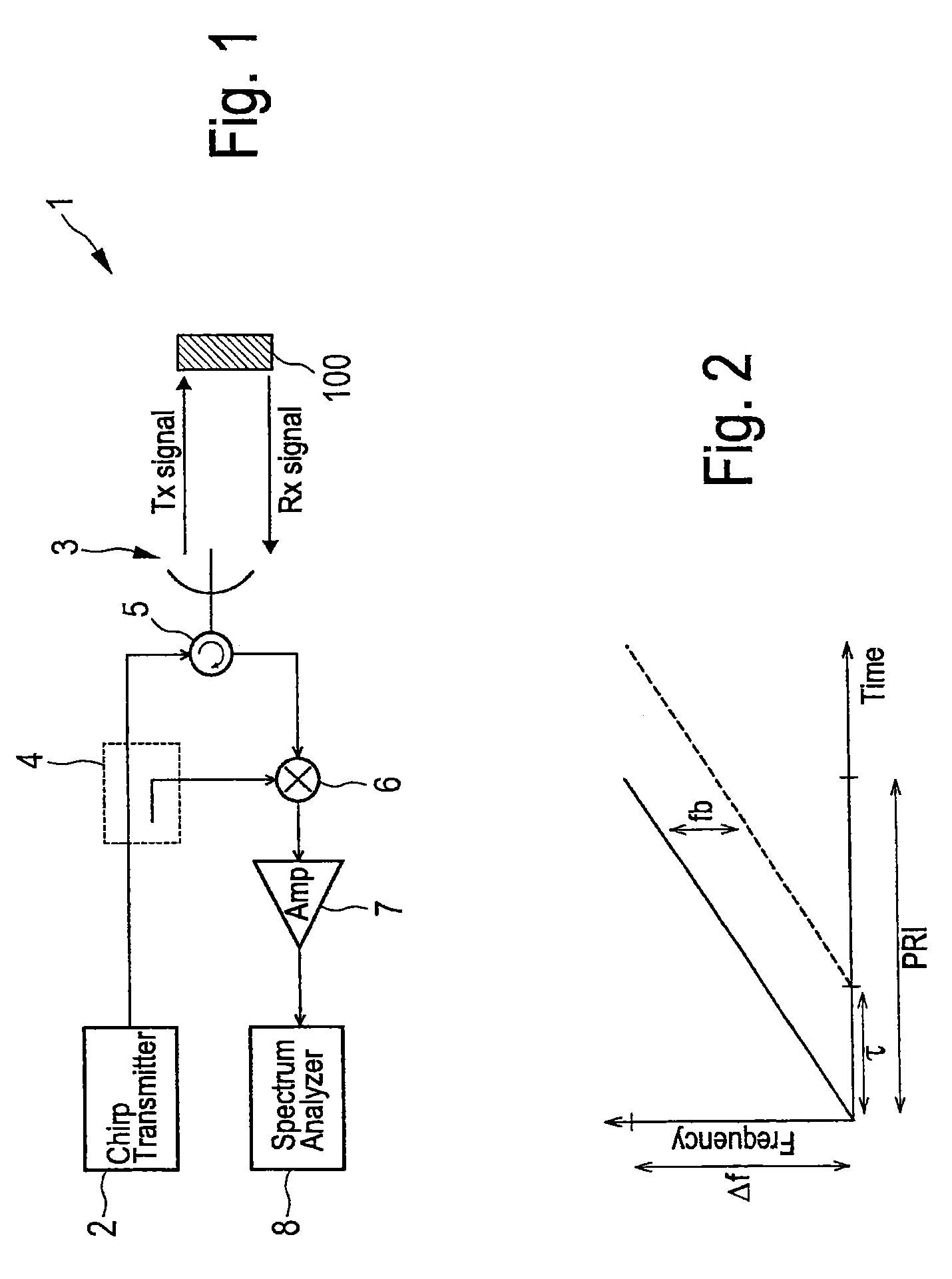
[0033]Referring now to the drawings, wherein like reference numerals designate identical or corresponding parts throughout the several views, FIG. 1 shows an embodiment of a conventional FMCW radar apparatus 1. A thorough explanation of FMCW is given in G. Brooker, “Understanding Millimeter Wave FMCW Radars”, 1st International Conference on Sensing Technology, Nov. 21-23, 2005, Palmerston North, New Zealand, p. 152-157. Such a FMCW radar 1 transmits a continuous wave signal that is frequency modulated (frequency is changing with time) to produce a chirp pulse by a chirp transmitter 2. This is transmitted to the object 100 (e.g. included in a scene) to be examined by a co-located (monostatic) antenna 3 and is also fed to the receiver via a coupler 4. Depending upon the properties of the object 100 the transmitted signal will be reflected by the object 100 and be received by the receiver of the FMCW radar, i.e. the co-located antenna 3. A duplexer or circulator 5 serves for time multi...


PUM


Abstract

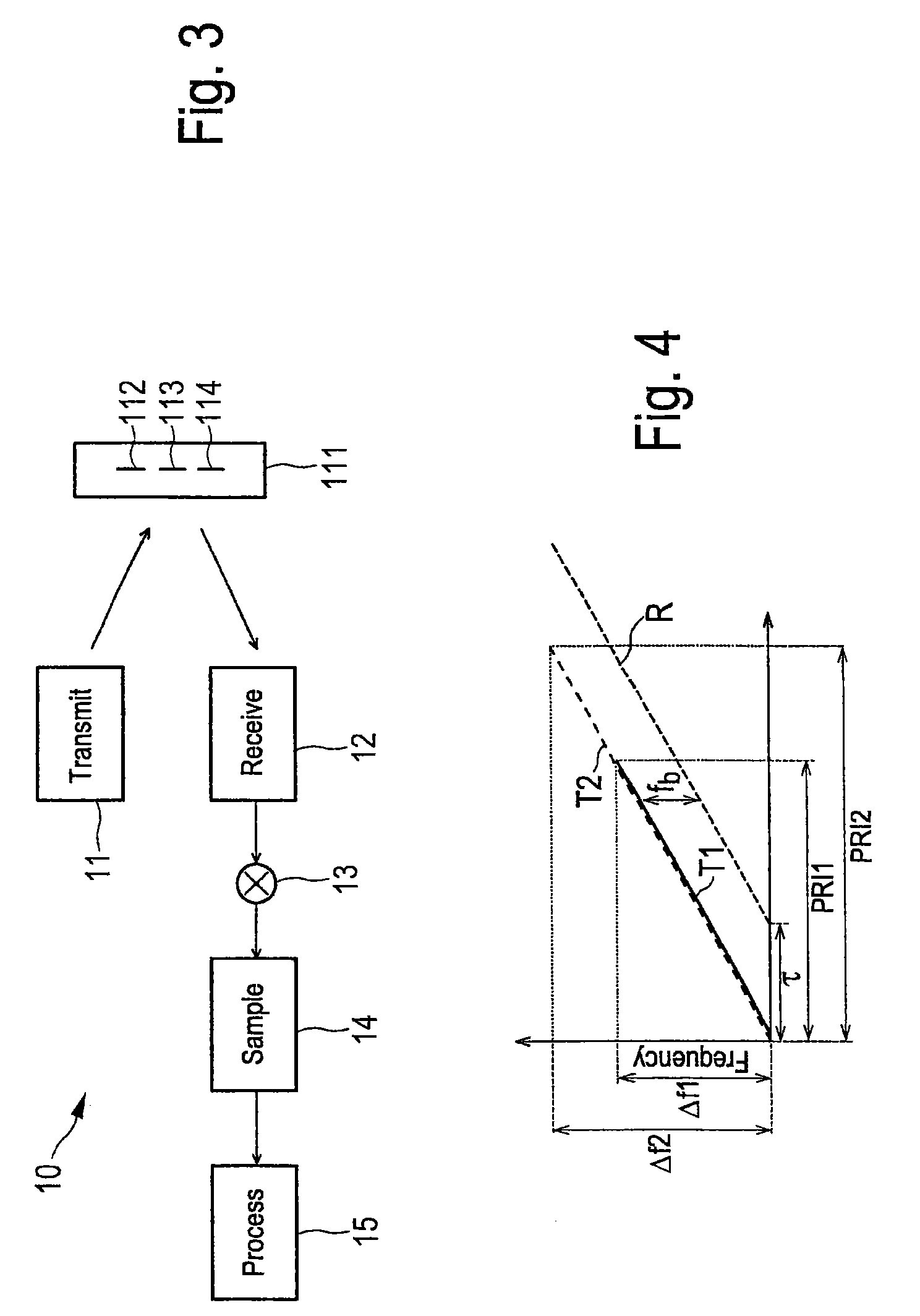
A radar apparatus for obtaining a higher range resolution than conventional radar apparatus without increasing the bandwidth comprises a transmitter antenna that transmits a frequency modulated transmit signal having a transmit bandwidth and a receiver antenna that receives a receive signal reflected from said scene in response to the transmission of said transmit signal. A mixer mixes said receive signal with said transmit signal to obtain a mixed receive signal, a sampling unit samples said mixed receive signal to obtain receive signal samples from a period of said receive signal, and a processor processes said receive signal samples by defining a measurement matrix and determines the positions of one or more targets of the scene by applying compressive sensing using said measurement matrix and said receive signal samples.

Description

CROSS-REFERENCE TO RELATED APPLICATION[0001]The present application claims the benefit of the earlier filing date of EP 11169360.2 filed in the European Patent Office on Jun. 9, 2011, the entire content of which application is incorporated herein by reference.BACKGROUND[0002]1. Field of the Disclosure[0003]The present disclosure relates to a radar apparatus and a corresponding radar method. Further, the present disclosure relates to a processing apparatus and method for use in such a radar apparatus and method, respectively. Still further, the present disclosure relates to a computer program for implementing said processing method and to a computer readable non-transitory medium storing such a computer program.[0004]2. Description of Related Art[0005]The range resolution of frequency modulated continuous wave (FMCW) radar systems improves (gets finer) by increasing the bandwidth of the transmitted chirp. Conventionally, the information about the range of the targets is extracted wit...

Claims


Application Information

Patent Timeline
Patent Type & Authority Patents(United States)
IPC IPC(8): G01S13/08
CPCG01S7/354G01S13/282G01S13/34
Inventor NOGUEIRA-NINE, JUAN
Owner SONY CORP
Learn More