
Setting zero bits in architectural register for storing destination operand of smaller size based on corresponding zero flag attached to renamed physical register

a technology of architectural register and destination operand, applied in the field of data processing systems, can solve the problems of inefficient use of physical register resources, large physical overhead, and inability to push these zero values, so as to avoid unnecessary addition of additional delay and save energy and circuitry resources.

Active Publication Date: 2015-03-03
ARM LTD
View PDF4 Cites 0 Cited by
  • Summary
  • Abstract
  • Description
  • Claims
  • Application Information

AI Technical Summary

Benefits of technology

The present technology suggests a way to improve efficiency in storing and processing data in a computer processor. Rather than storing zero values as individual elements in a register, this technique stores one or more symbols to represent the zero values. This is done by using less hardware and consuming less energy. The technology also suggests a way to optimally allocate physical registers to store the destination operand, which saves resources and allows for more efficient use of registers. Additionally, the technology avoids adding delay to critical paths by storing and reading the destination operand from the architectural register circuitry without unnecessary additional delay. The technical effects of the technology include improved efficiency, reduced resource consumption, and improved processing performance.

Problems solved by technology

However, a disadvantage with this approach is that a larger amount of physical overhead is required to store all of the zero values which effectively contain no useful information.
Furthermore, energy is consumed in pushing these zero values along the data path of the processor system.
Accordingly, inefficient use of the physical register resources provided can constrain the degree of out-of-order processing which may be achieved and the amount of speculation which may be supported.

Method used


Image

  • Setting zero bits in architectural register for storing destination operand of smaller size based on corresponding zero flag attached to renamed physical register
  • Setting zero bits in architectural register for storing destination operand of smaller size based on corresponding zero flag attached to renamed physical register
  • Setting zero bits in architectural register for storing destination operand of smaller size based on corresponding zero flag attached to renamed physical register

Examples


Embodiment Construction

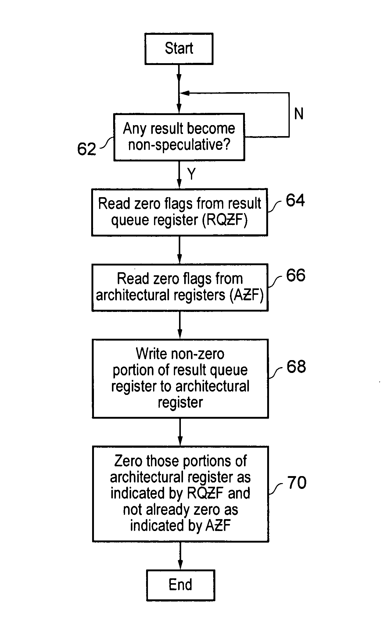
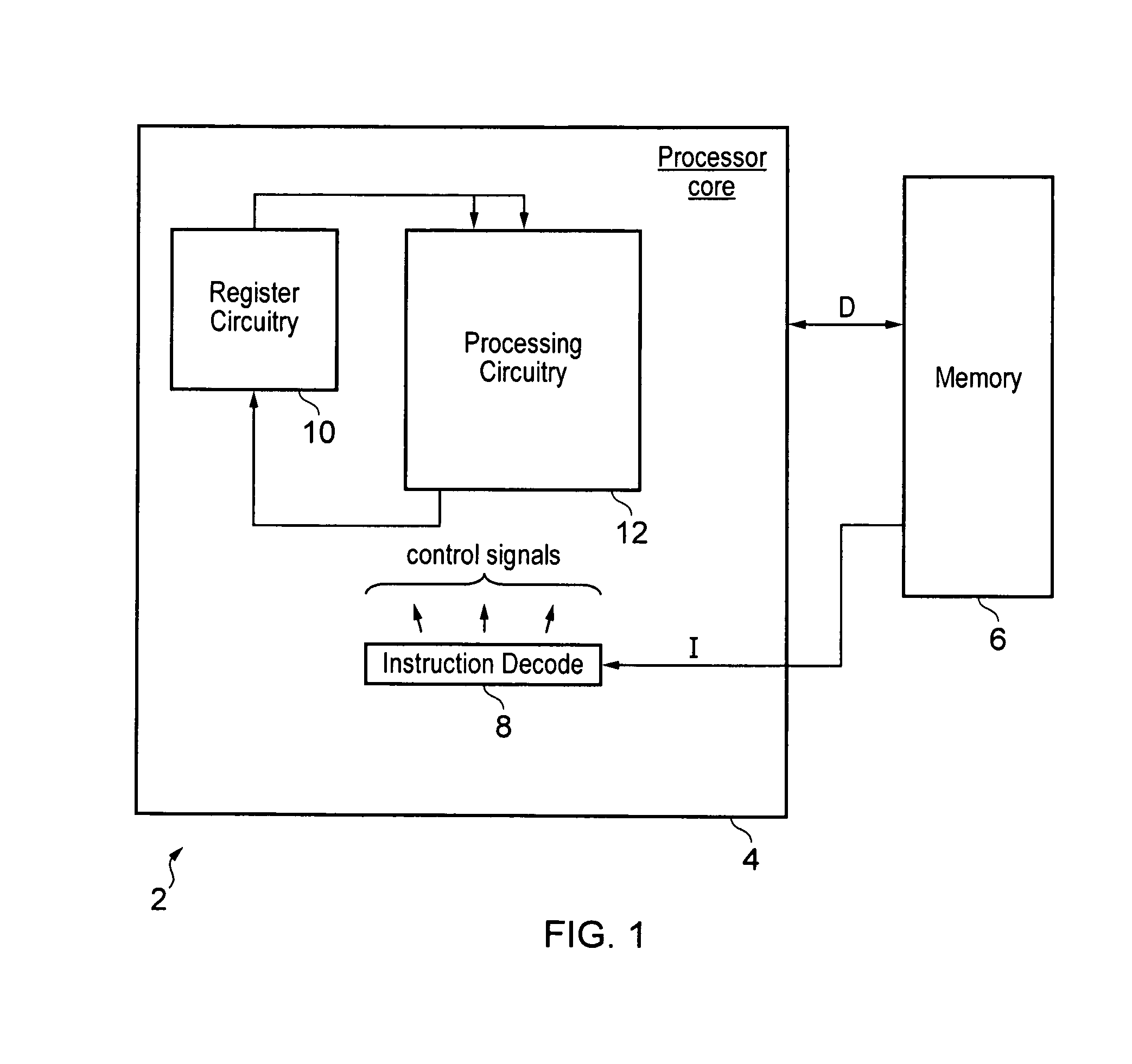
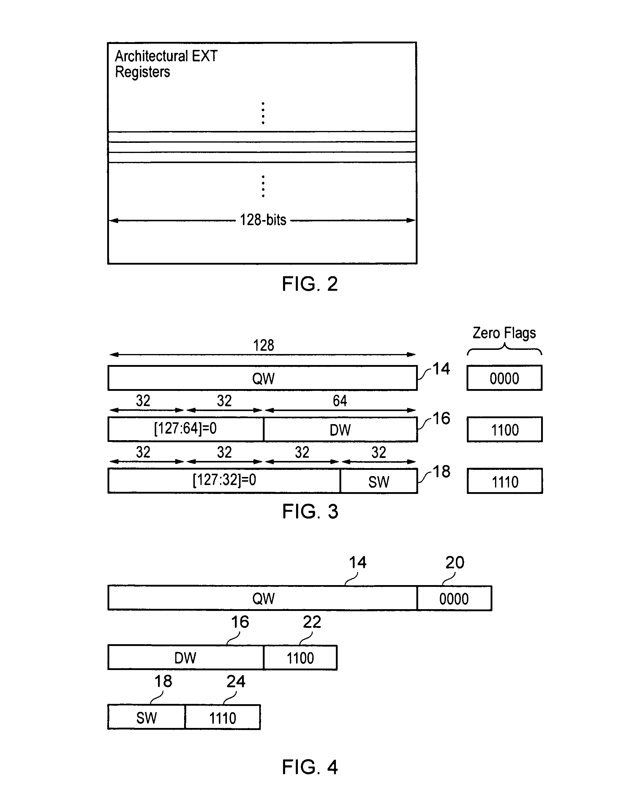
[0043]FIG. 1 schematically illustrates a data processing system 2 including a processor core 4 and a memory 6. The memory 6 stores data values to be manipulated and program instructions for controlling manipulation of those data values. The program instructions are fetched and decoded by instruction decode circuitry 8 to generate control signals which control register circuitry 10 and processing circuitry 12 to perform processing operations specified by those program instructions. The register circuitry 10 may include, for example, normal general purpose registers and extension registers. The normal general purpose registers may be 32 or 64 bit registers. The extension registers may be, for example, 128-bit registers used to store either single word, double word or quad word operands. The present technique will be described further in relation to the extension registers having a bit width of 128-bits, but the present technique could equally be applied to the general purpose register...


PUM


Abstract

A data processing system is provided in which destination operands to be stored within architectural registers are constrained to have zero values added as prefixes in order that the architectural register value has a fixed bit width irrespective of the bit width of the destination operand being written thereto. Instead of adding these zero values everywhere in the data path, they are instead represented by zero flags in at least the physical registers utilized for register renaming operations and in the result queue prior to results being written to the architectural register file. This saves circuitry resources and reduces energy consumption.

Description

BACKGROUND OF THE INVENTION[0001]1. Field of the Invention[0002]This invention relates to the field of data processing systems. More particularly, this invention relates to the management and manipulation of operands of different bit widths that have zero values added to form register values of a constant bit-width.[0003]2. Description of the Prior Art[0004]It is known to provide data processing systems that manipulate operands (source operands or destination operands) that have different bit-widths, such as single word operands (SW), double word operands (DW) and quad word operands (QW). Operands of these different bit widths may be stored within registers that have a constant bit-width, such as the width of a quad word. In some of these systems it is architecturally defined that when an operation of less than the register bit-width is written in to a register then it is prefixed with zero values filling the unused high-order portion of the register such that the full register is o...

Claims


Application Information

Patent Timeline
Patent Type & Authority Patents(United States)
IPC IPC(8): G06F9/30G06F1/32
CPCG06F9/30003G06F1/3234G06F9/30112G06F9/30014G06F9/30189G06F9/384
Inventor HARDAGE, JAMES NOLANHARRIS, GLEN ANDREWGLASS, MARK CARPENTER
Owner ARM LTD
Learn More