Engine having thermostat and system thereof

a technology of thermostat and engine, applied in the direction of machines/engines, mechanical devices, operating means/release devices of valves, etc., can solve problems such as not actively coping with a change, and achieve the effect of improving the quality of exhaust gas and reducing fuel consumption

Inactive Publication Date: 2015-03-10
HYUNDAI MOTOR CO LTD +1
View PDF27 Cites 6 Cited by
  • Summary
  • Abstract
  • Description
  • Claims
  • Application Information

AI Technical Summary

Benefits of technology

[0015]The present invention has been made in an effort to provide an engine having a thermostat and a system thereof having advantages of reducing fuel consumption and improving a quality of an exhaust gas by more quickly heating a temperature of a coolant that circulates an engine and a thermostat.
[0023]The control unit may stop operation of the heater and block the flow of the coolant that is supplied to the heater through a heating line adjustment valve, if the temperature of the coolant is equal to or larger than a predetermined value.
[0030]In an engine system having a thermostat of the present invention, in a state in which a first flow channel that is connected to a radiator is blocked in a thermostat casing, by blocking a second flow channel that is connected an engine and by enabling a coolant to circulate an engine, a heater, and a thermostat, a temperature of the coolant can be more quickly heated. Therefore, fuel consumption can be reduced, and a quality of an exhaust gas can be further improved.

Problems solved by technology

Such a mechanical thermostat operates according to an opening and closing temperature that is set to a predetermined temperature, simply opens and closes only in a predetermined temperature, and does not actively cope with a change such as driving circumstances or a situation of a vehicle.

Method used


Image

  • Engine having thermostat and system thereof
  • Engine having thermostat and system thereof
  • Engine having thermostat and system thereof

Examples


Embodiment Construction

[0036]Reference will now be made in detail to various embodiments of the present invention(s), examples of which are illustrated in the accompanying drawings and described below. While the invention(s) will be described in conjunction with exemplary embodiments, it will be understood that present description is not intended to limit the invention(s) to those exemplary embodiments. On the contrary, the invention(s) is / are intended to cover not only the exemplary embodiments, but also various alternatives, modifications, equivalents and other embodiments, which may be included within the spirit and scope of the invention as defined by the appended claims.

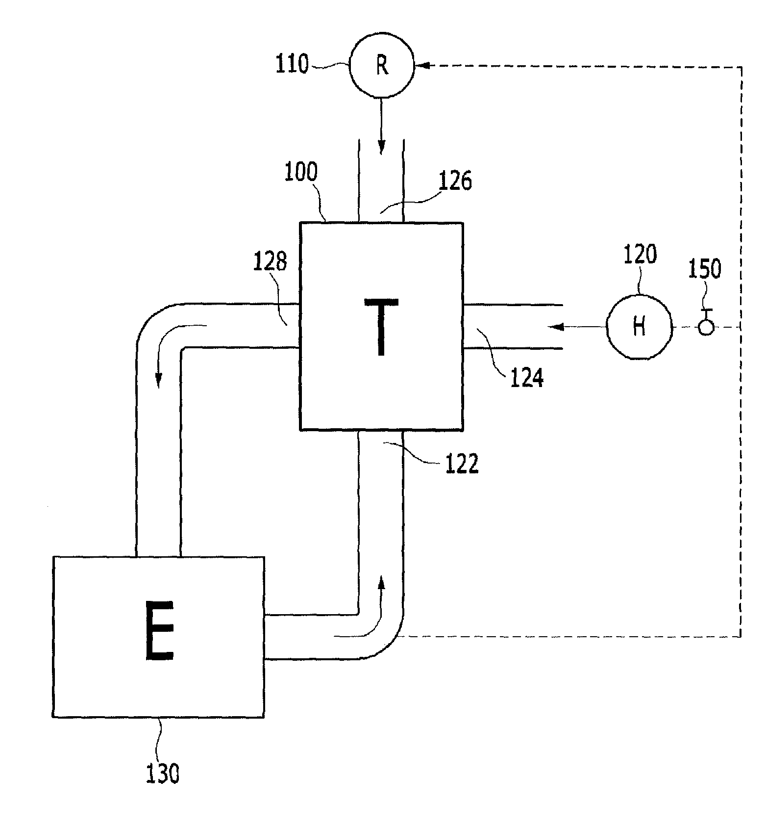
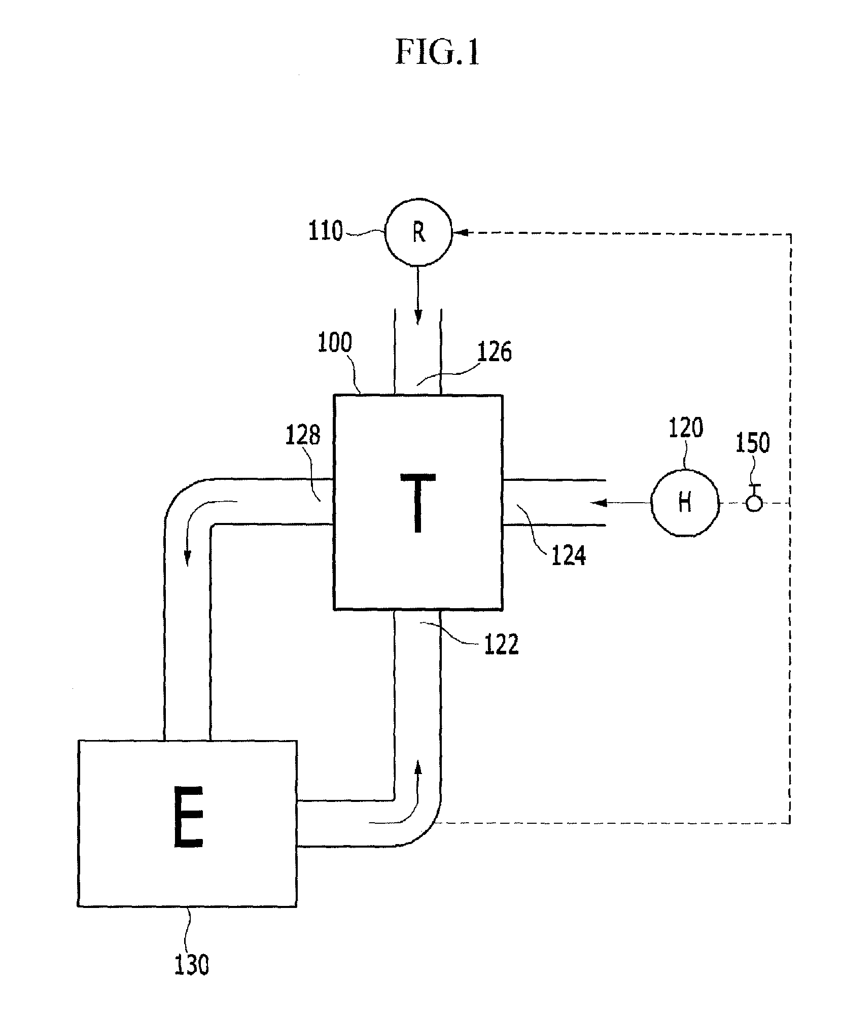
[0037]FIG. 1 is a schematic diagram of an engine system having a thermostat according to various embodiments of the present invention. Referring to FIG. 1, the engine system having a thermostat includes an engine 130, a thermostat 100, a heater 120, an engine exhaust flow channel 122, an engine inflow flow channel 128, a heater exhaus...


PUM


Abstract

An engine system may include a thermostat casing connected to a first, second, third, and fourth flow channels, a valve guide in which a main valve that opens and closes the first flow channel is formed at one side, a closing valve that opens and closes the second flow channel is formed at the other side, and a bypass valve is formed adjacent to the closing valve, an elastic member that elastically supports the valve guide to enable the main valve to block the first flow channel and the closing valve to block the second flow channel, a driver that moves the valve guide so that the main valve opens the first flow channel and the closing valve opens the second flow channel according to a temperature of a coolant, and a control unit that controls the temperature and a flow of the coolant by controlling the driver.

Description

CROSS-REFERENCE TO RELATED APPLICATION[0001]The present application claims priority of Korean Patent Application Number 10-2012-0155365 filed Dec. 27, 2012, the entire contents of which application are incorporated herein for all purposes by this reference.BACKGROUND OF INVENTION[0002]1. Field of Invention[0003]The present invention relates to an engine having a thermostat and a system thereof that actively control a temperature of a coolant by converting a flow channel of the coolant according to a temperature of the coolant that is circulated to prevent overheating.[0004]2. Description of Related Art[0005]A vehicle thermostat is installed between an engine and a radiator and maintains a coolant in a predetermined temperature range by adjusting a flux flowing to a radiator while being automatically opened and closed according to a temperature change of a coolant.[0006]In a mechanical thermostat, a wax expands according to a temperature of a coolant, and a piston causes an opening a...

Claims


Application Information

Patent Timeline
Patent Type & Authority Patents(United States)
IPC IPC(8): F01P7/00F01P7/16
CPCF01P7/16F01P7/167F01P2060/18F16K31/00
Inventor LEE, PHILGIKIM, GYUHWANPARK, JAE SUKKIM, YONG JEONG
Owner HYUNDAI MOTOR CO LTD
Why Eureka
Try Eureka