Method and system for controlling exhaust gas flow in engine system

a technology of engine system and exhaust gas flow, which is applied in the direction of electrical control, machine/engine, electric control of exhaust gas, etc., can solve the problems of excessive harmful material of exhaust gas, substantially low exhaust gas temperature, and delay in the activation time of post processing system, so as to improve the quality of exhaust gas

Active Publication Date: 2018-03-06
HYUNDAI MOTOR CO LTD
View PDF16 Cites 0 Cited by
  • Summary
  • Abstract
  • Description
  • Claims
  • Application Information

AI Technical Summary

Benefits of technology

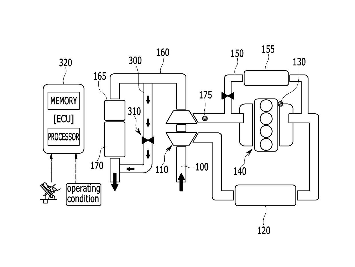
[0008]The present invention has been made in an effort to provide a method for controlling an exhaust gas flow in an engine system having advantages of maintaining exhaust gas purification rate and exhaust gas quality by preventing the temperature decrement of the catalyst unit when uncombusted exhaust gas passes a catalyst unit.
[0012]In accordance with the present invention for realizing the object, the uncombusted exhaust gas may be controlled to bypass the catalyst unit to uniformly maintain the catalyst unit temperature and the quality of exhaust gas may be improved, when the engine is in an over-run condition, the coolant temperature is less than a predetermined value, and a lambda value is greater than a predetermined value.

Problems solved by technology

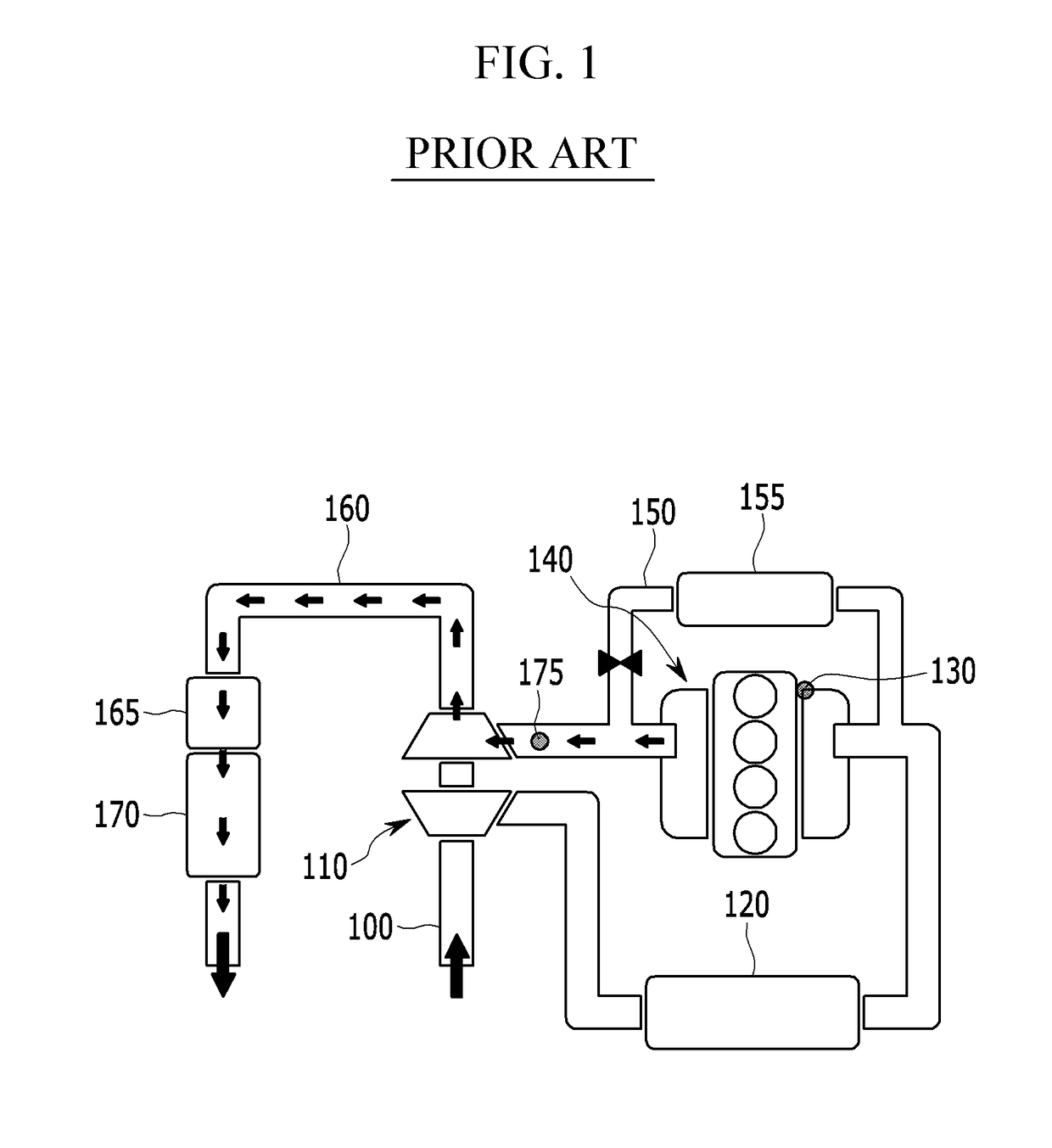
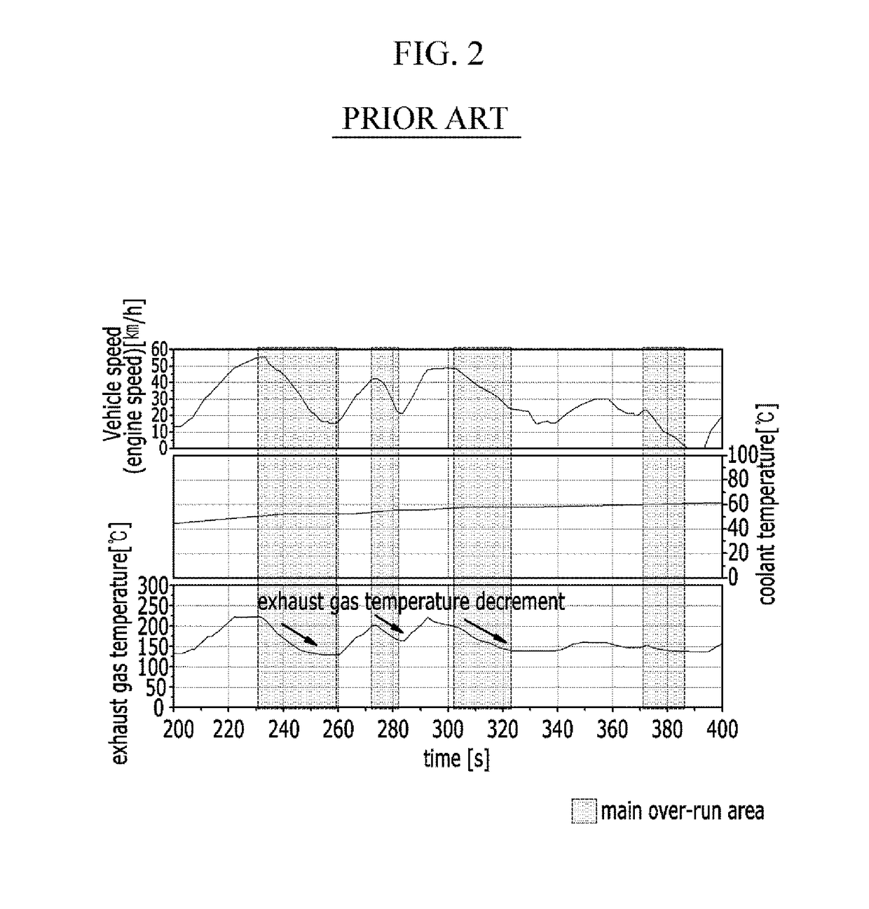
Specifically, exhaust gas temperature is substantially low in a cold state of an engine (e.g., coolant temperature is less than 90 degrees Celsius), and excessive harmful material of exhaust gas is generated until the post processing device is activated.
However, it may be possible to increase the exhaust gas temperature through fuel combustion, an intake air may be transferred to a post processing system without combustion in an over-run condition (e.g., coasting state, fuel unburned state), and therefore the post processing system may be cooled by the unburned intake air and the activation time of the post processing system may be delayed.

Method used


Image

  • Method and system for controlling exhaust gas flow in engine system
  • Method and system for controlling exhaust gas flow in engine system
  • Method and system for controlling exhaust gas flow in engine system

Examples


Embodiment Construction

[0018]It is understood that the term “vehicle” or “vehicular” or other similar term as used herein is inclusive of motor vehicles in general such as passenger automobiles including sports utility vehicles (SUV), buses, trucks, various commercial vehicles, watercraft including a variety of boats and ships, aircraft, and the like, and includes hybrid vehicles, electric vehicles, combustion, plug-in hybrid electric vehicles, hydrogen-powered vehicles and other alternative fuel vehicles (e.g. fuels derived from resources other than petroleum).

[0019]Although exemplary embodiment is described as using a plurality of units to perform the exemplary process, it is understood that the exemplary processes may also be performed by one or plurality of modules. Additionally, it is understood that the term controller / control unit refers to a hardware device that includes a memory and a processor. The memory is configured to store the modules and the processor is specifically configured to execute ...


PUM


Abstract

A method and system for controlling an exhaust gas flow in an engine system are provided. The method includes detecting operating conditions of an engine and operating a valve that is disposed on a line bypassing a catalyst unit based on the operating conditions such that exhaust gas bypasses the catalyst unit. The operating conditions include a vehicle speed, an engine rotation speed, a fuel injection amount, an accelerator pedal signal, a coolant temperature, or a lambda value of exhaust gas.

Description

CROSS-REFERENCE TO RELATED APPLICATION[0001]This application claims priority to and the benefit of Korean Patent Application No. 10-2014-0142072 filed in the Korean Intellectual Property Office on Oct. 20, 2014, the entire contents of which are incorporated herein by reference.BACKGROUND[0002](a) Field of the Invention[0003]The present invention is related to a method and system for controlling an exhaust gas flow in an engine system that safely maintains a temperature of a diesel particulate filter (DPF) or a diesel oxidation catalyst (DOC) in an over-run condition of an engine to uniformly maintain a purification rate of exhaust gas.[0004](b) Description of the Related Art[0005]Generally, a diesel oxidation catalyst (DOC) and a diesel particulate filter (DPF), a nitrogen oxide purifying unit (LNT, lean NOx trap), and a selective catalytic reduction unit (SCR) have been considered in diesel engines of vehicle to cope with the exhaust gas regulations. The post processing system such...

Claims


Application Information

Patent Timeline
Patent Type & Authority Patents(United States)
IPC IPC(8): F01N3/20F01N3/021F02M26/05F02M26/23
CPCF01N3/2053F01N3/021F01N2410/00Y02T10/20F01N2900/1404F02M26/05F02M26/23F01N2900/08Y02A50/20Y02T10/12F01N9/00F02D43/00F01N2900/10
Inventor NAM, KIHOON
Owner HYUNDAI MOTOR CO LTD
Why Eureka
Try Eureka