Engine system for controlling flow of exhaust gas

a technology of exhaust gas and engine, which is applied in the direction of machines/engines, electrical control, electric control of exhaust gas treatment, etc., can solve the problems of excessive exhaust of exhaust gas, delay in activation temperature reach time, and reduced temperature of post-processing system, so as to prevent the temperature of a catalyst unit from being reduced, the effect of improving the quality of exhaust gas

Active Publication Date: 2017-01-26
HYUNDAI MOTOR CO LTD
View PDF11 Cites 0 Cited by
  • Summary
  • Abstract
  • Description
  • Claims
  • Application Information

AI Technical Summary

Benefits of technology

[0011]Various aspects of the present invention are directed to providing an engine system for controlling flow of exhaust gas having advantages of improving quality of exhaust gas by preventing a temperature of a catalyst unit from being reduced when non-combustion exhaust gas passes through the catalyst unit like in an overrun condition.
[0024]In accordance with the engine system for controlling flow of exhaust gas according to various embodiments of the present invention as described above, the temperature of the catalyst unit may be stably maintained and the quality of the exhaust gas may be improved by controlling non-combustion exhaust gas of the engine to bypass the catalyst unit in an overrun condition.

Problems solved by technology

In this region, exhaust gas is excessively exhausted after the post processing device is activated.
However, in a case of overrun (coasting run, non-combustion state), intake air is discharged to an engine exhaust port without a combustion process which cools the post-processing system so that the temperature of the post-processing system is reduced and an activation temperature reach time may be delayed.

Method used


Image

  • Engine system for controlling flow of exhaust gas
  • Engine system for controlling flow of exhaust gas
  • Engine system for controlling flow of exhaust gas

Examples


Embodiment Construction

[0031]Reference will now be made in detail to various embodiments of the present invention(s), examples of which are illustrated in the accompanying drawings and described below. While the invention(s) will be described in conjunction with exemplary embodiments, it will be understood that the present description is not intended to limit the invention(s) to those exemplary embodiments. On the contrary, the invention(s) is / are intended to cover not only the exemplary embodiments, but also various alternatives, modifications, equivalents and other embodiments, which may be included within the spirit and scope of the invention as defined by the appended claims.

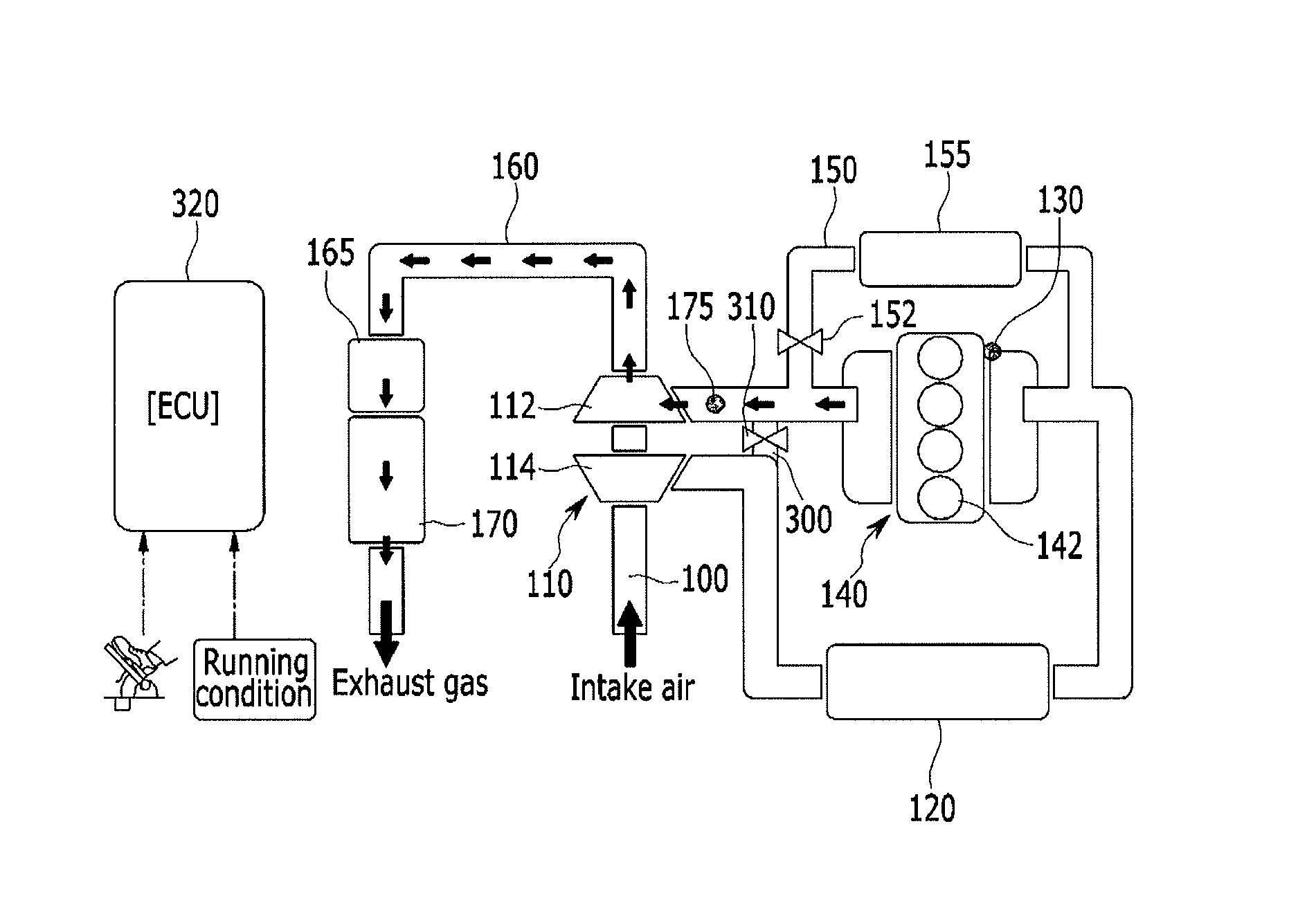
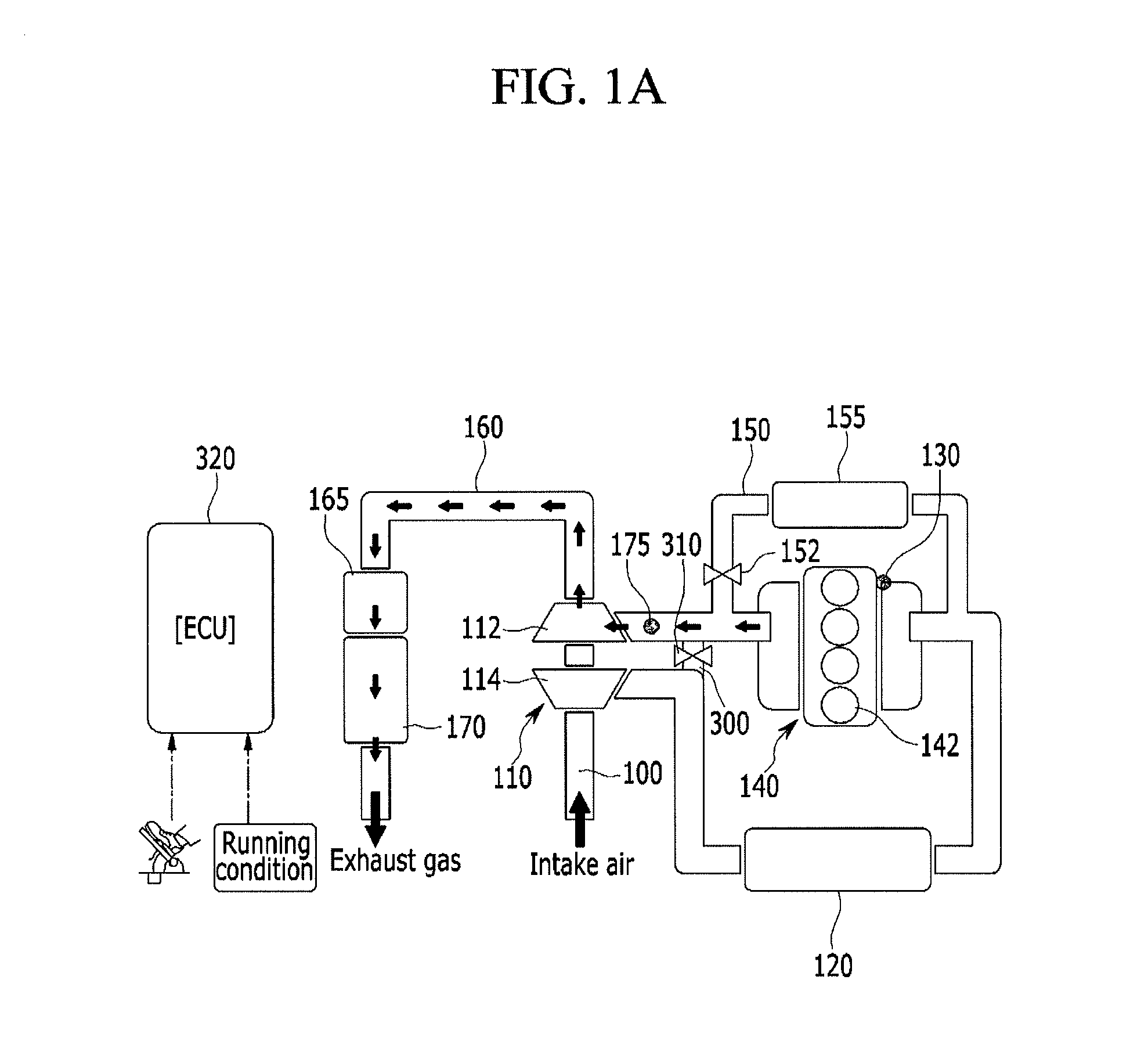
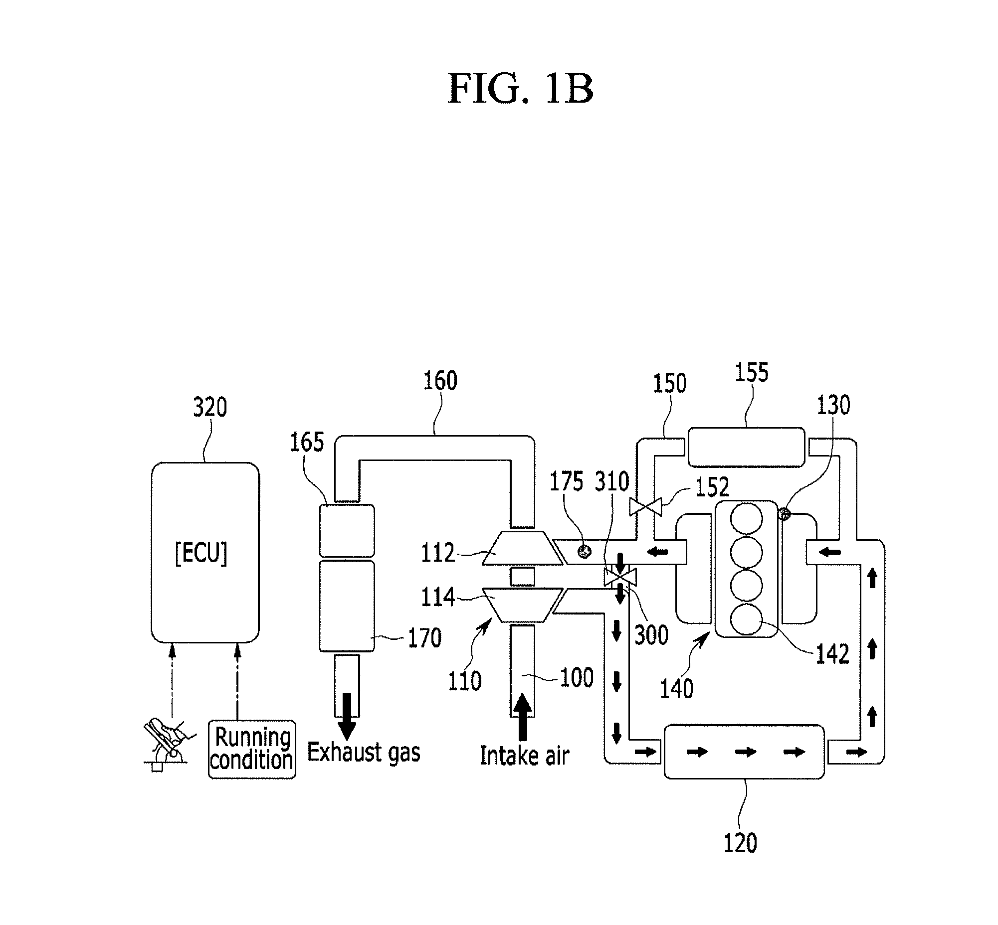
[0032]FIG. 1A and FIG. 1B are schematic diagrams illustrating an engine system for controlling flow of exhaust gas according to various embodiments of the present invention.

[0033]FIG. 1A shows a state where a bypass valve is closed, and FIG. 1B shows a state where the bypass valve is opened.

[0034]As shown in FIG. 1A and FIG. 1B, t...


PUM


Abstract

An engine system for controlling flow of exhaust gas may include an intake line to receive external air, an engine including a combustion chamber to combust the external air and a fuel supplied through the intake line, to generate driving torque, an exhaust line to exhaust the exhaust gas combusted in the combustion chamber of the engine, a turbocharger including a turbine operated according to exhaust gas flowing through the exhaust line and a compressor to compress the external air flowing through the intake line, a catalyst device to reduce a harmful component included in the exhaust gas passing through the turbine of the turbocharger, a bypass line branched from the exhaust line between the combustion chamber and the turbine and converged in the intake line between the compressor and the combustion chamber, and a bypass valve disposed in the bypass line to selectively open / close the bypass line.

Description

CROSS-REFERENCE TO RELATED APPLICATIONS[0001]The present application is a divisional of U.S. patent application Ser. No. 14 / 798,168, filed Jul. 13, 2015, which claims priority to Korean Patent Application No. 10-2014-0148304 filed Oct. 29, 2014, the entire contents of which are incorporated herein for all purposes by these references.BACKGROUND OF THE INVENTION[0002]Field of the Invention[0003]The present invention relates to an engine system for controlling flow of exhaust gas. More particularly, the present invention relates to an engine system for controlling flow of exhaust gas capable of stably maintaining a cleaning rate of exhaust gas by stably maintaining a temperature of a diesel oxidation catalyst (DOC) or a diesel particulate filter (DPF) in an overrun condition of an engine.[0004]Description of Related Art[0005]In recent years, in order to respond to limitations on exhaust gas in a passenger diesel engine, a diesel oxidation catalyst (DOC), a diesel particulate filter (D...

Claims


Application Information

Patent Timeline
Patent Type & Authority Applications(United States)
IPC IPC(8): F02B37/16
CPCF05B2220/40F02B37/168F02M26/06F02M26/15F02M26/23F02M26/38F02M26/42F02D41/123F01N3/021Y02T10/12F02M26/00F01N3/00F01N3/08F01N3/20F01N9/00F02B39/00F02D43/00
Inventor NAM, KIHOON
Owner HYUNDAI MOTOR CO LTD
Why Eureka
Try Eureka