Method for diagnosing a tank venting valve

a technology for venting valves and valve bodies, applied in the direction of machines/engines, electric control, combustion-air/fuel-air treatment, etc., can solve problems such as defects

Active Publication Date: 2016-04-19
ROBERT BOSCH GMBH
View PDF15 Cites 0 Cited by
  • Summary
  • Abstract
  • Description
  • Claims
  • Application Information

AI Technical Summary

Benefits of technology

[0011]As the effect of the control of the tank venting valve on the air system is taken into account during the diagnosis of the tank venting valve, using correction pressure pK, the opening time of the tank venting valve may be reduced. In this manner, the selectivity of the valve diagnosis is improved. In addition, the quality of the exhaust gas improves, since only a short-term disturbance in the optimum fuel / air mixture occurs. In the case of use of the internal combustion engine in a motor vehicle, the ride comfort is ultimately improved if an unnecessarily long disturbance in the fuel / air supply can be dispensed with.
[0014]The computer program of the present invention executes all of the steps of the method of the present invention, when it runs on a computing element. In this manner, it is possible to implement the method of the present invention in an existing tank venting system without having to make structural changes. A computer program product having program code for carrying out the method of the present invention, when the program is executed on a computer or control unit, may be stored on a machine-readable carrier.

Problems solved by technology

A defect is present, when the difference between the induction pipe pressure after the opening activation of the tank venting valve and prior to the opening activation of the tank venting valve is below a particular threshold value.

Method used


Image

  • Method for diagnosing a tank venting valve
  • Method for diagnosing a tank venting valve
  • Method for diagnosing a tank venting valve

Examples


Embodiment Construction

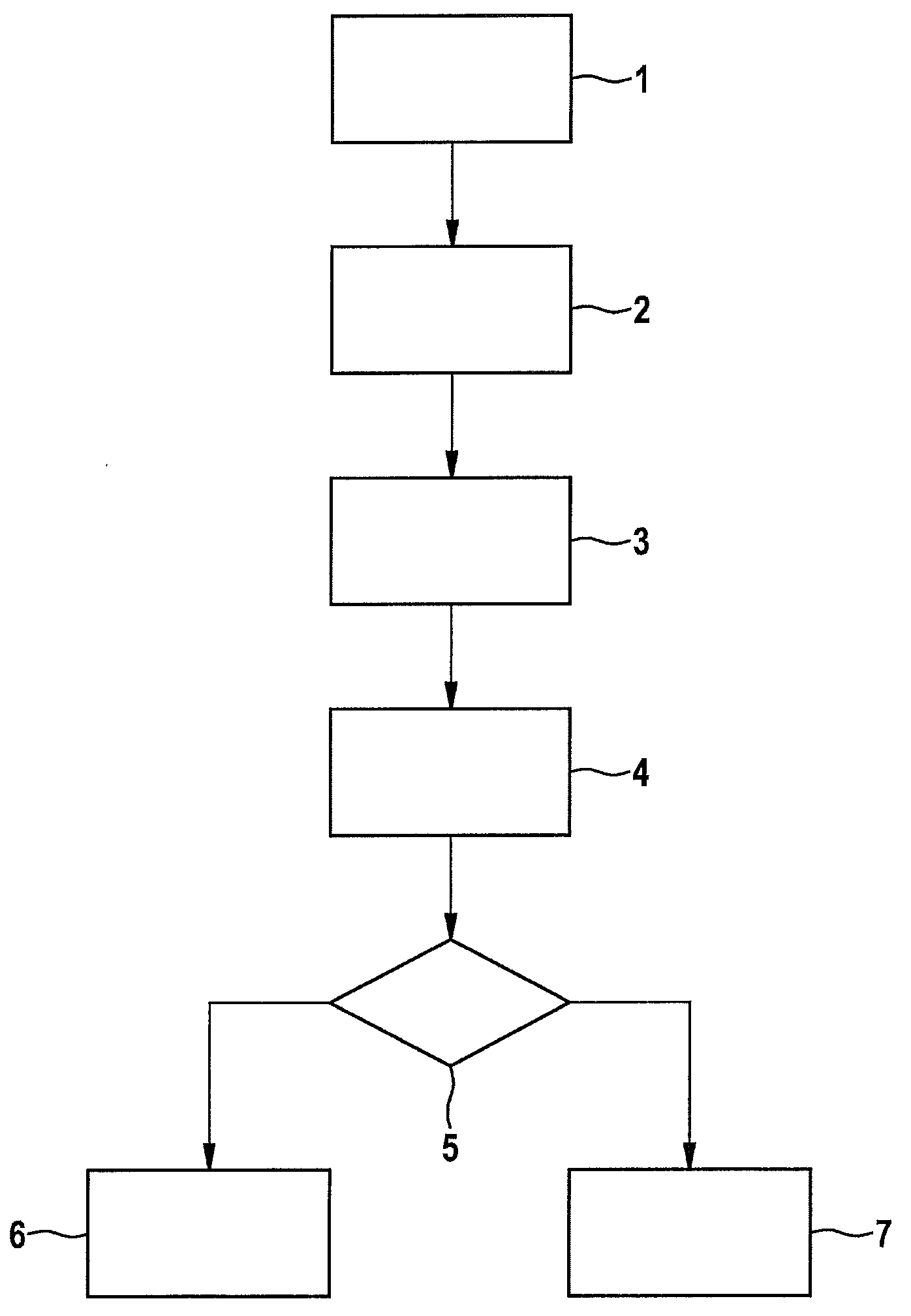
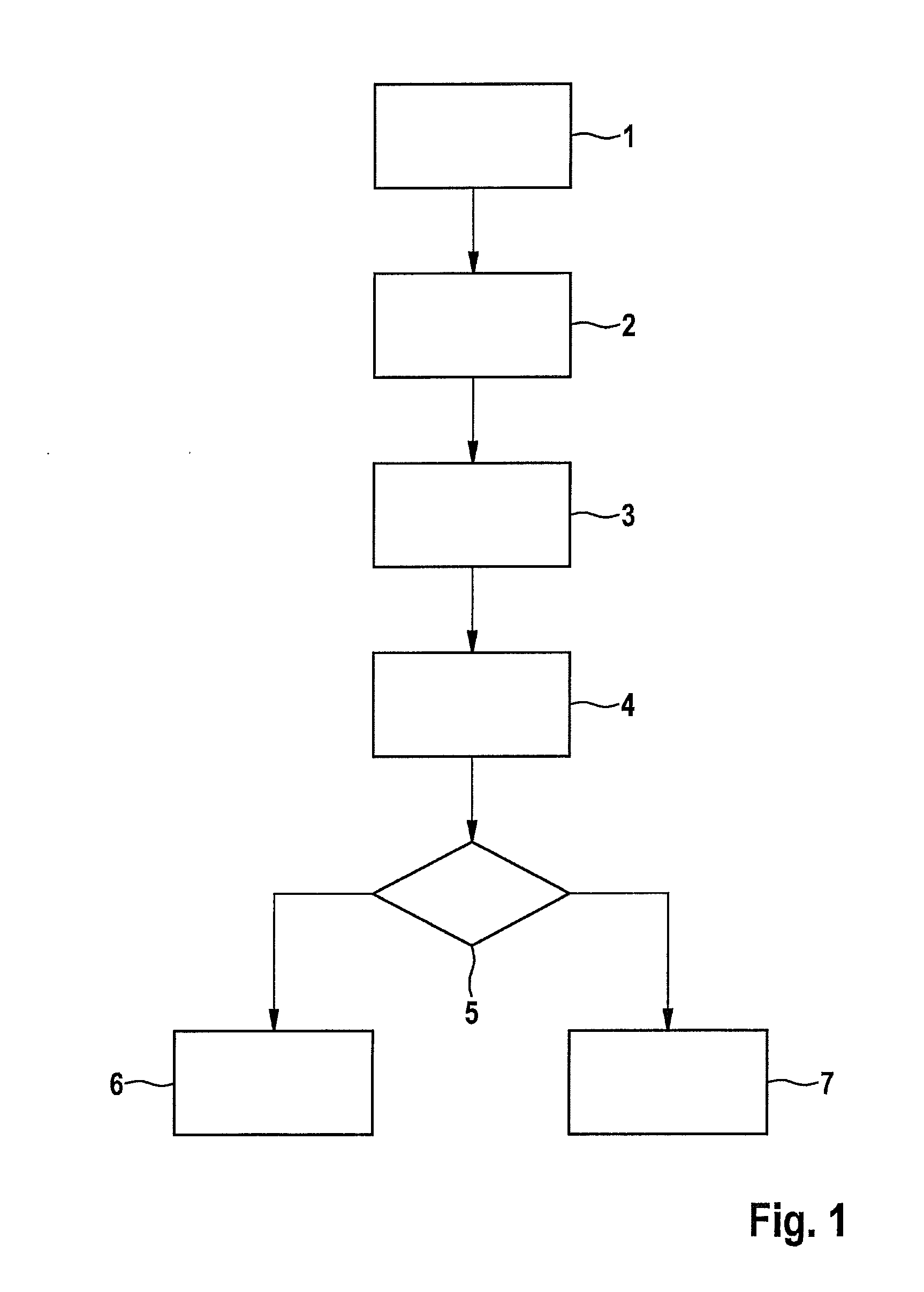
[0018]FIG. 1 shows a process diagram of a specific embodiment of the method of the present invention for diagnosing a tank venting valve. In method step 1, a first pressure p1 is measured by a pressure sensor in the induction pipe of an internal combustion engine having a tank venting system, for example, the internal combustion engine of a motor vehicle. In the suction mode of the internal combustion engine, this first pressure is less than the ambient pressure. In method step 2, the tank venting valve of the tank venting system is activated so as to open. When the tank venting valve is in working order, this results in the opening of the valve. When the opening activation ends, the tank venting valve closes again.

[0019]In method step 3, a second pressure p2 in the induction pipe of the internal combustion engine is now measured. Since by opening the tank venting valve, a fuel / air mixture flows out of the active carbon filter of the tank venting system, into the induction pipe of t...


PUM


Abstract

A method for diagnosing a tank venting valve. This includes measuring a first pressure p1 in the induction pipe of an internal combustion engine; activating the tank venting valve so as to open; measuring a second pressure p2 in the induction pipe of the internal combustion engine after the opening activation of the tank venting valve; calculating a control value K by subtracting the first induction pipe pressure p1 from a second induction pipe pressure p2 and adding a correction pressure pK, which is calculated from the leakage air adaptation of an internal combustion engine; and detecting A defect of the tank venting valve, when the control value K falls below a threshold value.

Description

FIELD OF THE INVENTION[0001]The present invention relates to a method for diagnosing a tank venting valve. In addition, it relates to a computer program, which executes all of the steps of the method of the present invention when it runs on a computing element, as well as to a computer program product including program code, which is stored on a machine-readable carrier for performing the method of the present invention, when the program is executed on a computer or control unit.BACKGROUND INFORMATION[0002]Today's internal combustion engines include tank venting systems, in which fuel evaporated in the tank is stored in an active carbon filter, which is connected to the induction pipe of the internal combustion engine via a tank venting valve capable of being closed off. In response to opening the tank venting valve, air is drawn in via a connection of the active carbon filter to the environment, the air entraining the temporarily stored fuel and supplying it for combustion. Using t...

Claims


Application Information

Patent Timeline
Patent Type & Authority Patents(United States)
IPC IPC(8): G01M15/04F02M25/08F02M35/10F02D41/00
CPCF02M25/0809F02M25/0827F02M25/0836F02M35/1038F02D41/0037F02D2200/0406
Inventor SALOMON, STEFANNUSSER, UWE
Owner ROBERT BOSCH GMBH
Why Eureka
Try Eureka