Planar coil element

a technology of planar coil and element, applied in the direction of transformers/inductances magnetic cores, inductances, inductances with magnetic cores, etc., to achieve the effect of high magnetic permeability, high strength, and high magnetic permeability

Active Publication Date: 2015-03-10
TDK CORPARATION
View PDF12 Cites 25 Cited by
  • Summary
  • Abstract
  • Description
  • Claims
  • Application Information

AI Technical Summary

Benefits of technology

[0007]In order to solve the above problem, it is an object of the present invention to provide a planar coil element that achieves both high strength and high magnetic permeability.
[0009]In the planar coil element, the quantitative ratio of inclined particles to total particles of the first metal magnetic powder contained in the metal magnetic powder-containing resin in the through hole provided in the magnetic core of the coil unit is higher than the quantitative ratio of inclined particles to total particles of the first metal magnetic powder contained in the metal magnetic powder-containing resin provided in other than the through hole. Therefore, many of particles of the first metal magnetic powder in the magnetic core are inclined particles whose major axes are inclined with respect to the thickness direction and the planar direction of the substrate. Therefore, the planar coil element has improved strength as compared to when the major axes of particles of the first metal magnetic powder contained in the metal magnetic powder-containing resin provided in the through hole are oriented in the thickness direction of the substrate, and has improved magnetic permeability as compared to when the major axes of particles of the first metal magnetic powder contained in the metal magnetic powder-containing resin provided in the through hole are oriented in the planar direction of the substrate, and thus achieves both high order of strength and magnetic permeability.
[0010]The first metal magnetic powder may have an average aspect ratio of 2.0 to 3.2. In this case, high magnetic permeability can be achieved.
[0011]Further, the planar coil element may further include a second metal magnetic powder contained in the metal magnetic powder-containing resin and having an average particle size smaller than that of the first metal magnetic powder. In this case, particles of the second metal magnetic powder enter the gaps between particles of the first metal magnetic powder, which makes it possible to increase the amount of metal magnetic powder contained in the metal magnetic powder-containing resin and therefore to achieve high magnetic permeability.
[0014]Further, a ratio of the average particle size of the second metal magnetic powder to the average particle size of the first metal magnetic powder may be 1 / 32 to 1 / 8. The use of the second metal magnetic powder having a small average particle size makes it possible to achieve high magnetic permeability.
[0015]According to the present invention, it is possible to provide a planar coil element that achieves both high strength and high magnetic permeability.

Problems solved by technology

However, the above-described planar coil element according to a conventional art has the following problem.

Method used


Image

  • Planar coil element
  • Planar coil element
  • Planar coil element

Examples


Embodiment Construction

[0031]Hereinbelow, a preferred embodiment of the present invention will be described in detail with reference to the accompanying drawings. It is to be noted that in the following description, the same elements or elements having the same function are represented by the same reference numerals and description thereof will not be repeated.

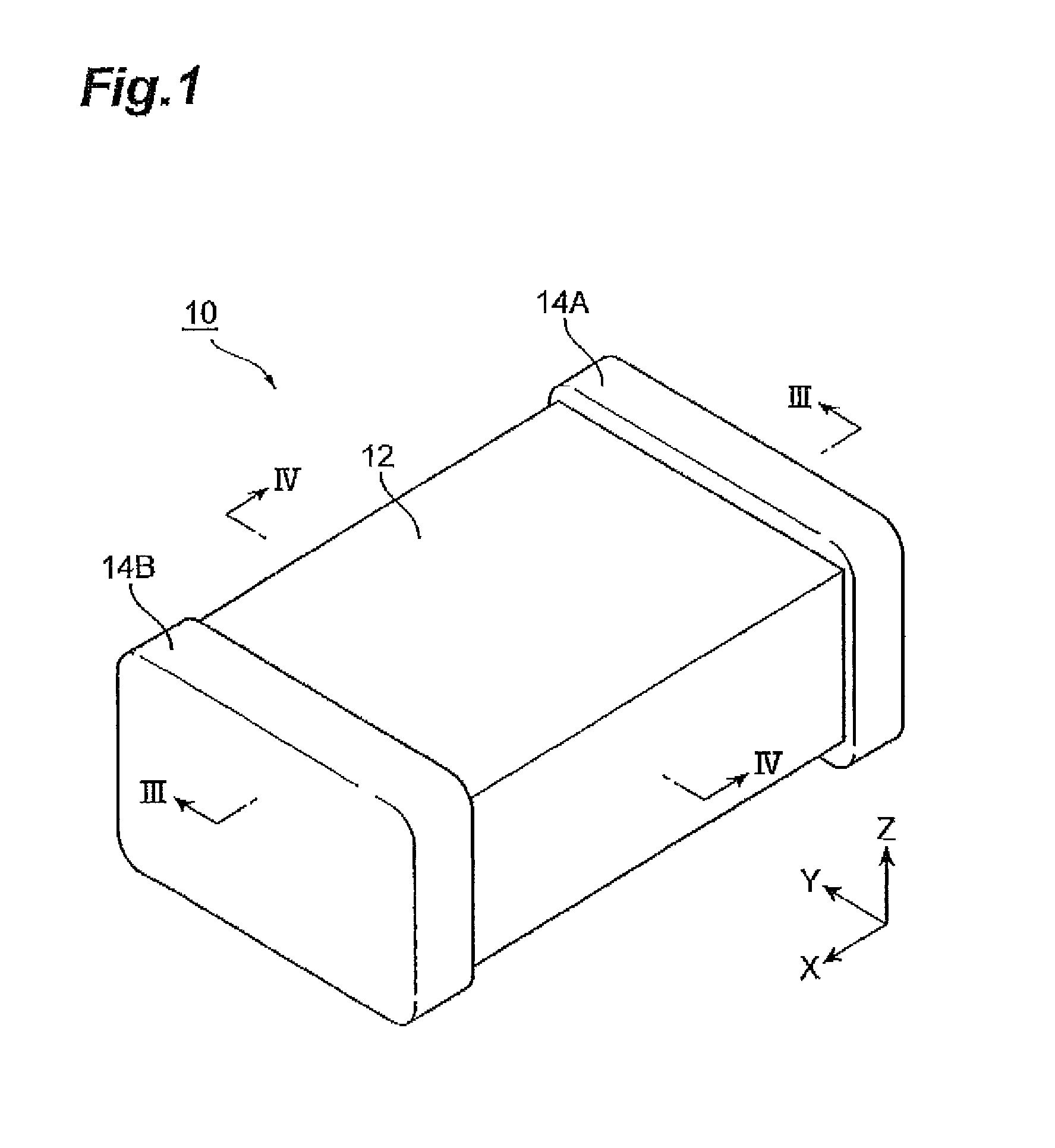
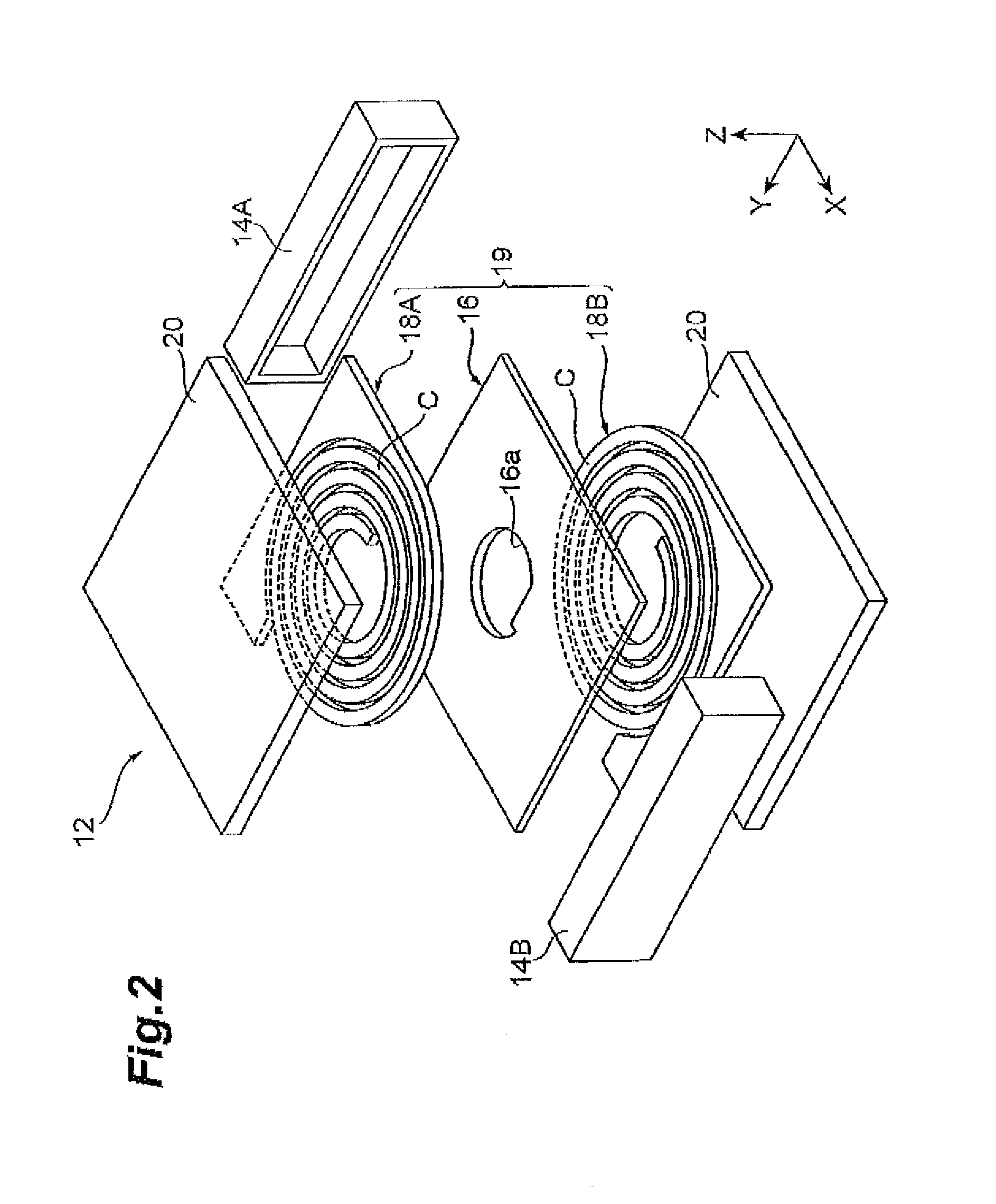
[0032]First, the structure of a planar coil element according to an embodiment of the present invention will be described with reference to FIGS. 1 to 4. For convenience of description, as shown in the drawings, X-, Y-, and Z-coordinates are set. More specifically, the thickness direction of the planar coil element is defined as a Z direction, a direction in which external terminal electrodes are opposed to each other is defined as an X direction, and a direction orthogonal to the X direction and the Z direction is defined as a Y direction.

[0033]A planar coil element 10 includes a main body 12 having a rectangular parallelepiped shape and a pair of ...


PUM

PropertyMeasurementUnit
aspect ratioaaaaaaaaaa
heightaaaaaaaaaa
heightaaaaaaaaaa

Abstract

In a planar coil element, the quantitative ratio of inclined particles to total particles of a first metal magnetic powder contained in a metal magnetic powder-containing resin provided in a through hole of a coil unit is higher than the quantitative ratio of inclined particles to total particles of the first metal magnetic powder contained in the metal magnetic powder-containing resin provided in other than the through hole, and many of particles of the first metal magnetic powder in the magnetic core are inclined particles whose major axes are inclined with respect to the thickness direction and the planar direction of a substrate. Therefore, the planar coil element has improved strength as compared to a planar coil element shown in FIG. 9A and has improved magnetic permeability as compared to a planar coil element shown in FIG. 9B.

Description

BACKGROUND OF THE INVENTION[0001]1. Field of the Invention[0002]The present invention relates to a planar coil element.[0003]2. Related Background Art[0004]Surface mount-type planar coil elements are conventionally used in various electrical products such as household devices and industrial devices. In particular, small portable devices have come to be required to obtain two or more voltages from a single power source to drive individual devices due to enhanced functions. Therefore, surface mount-type planar coil elements are used also as power sources to satisfy such a requirement.[0005]One of such planar coil elements is disclosed in, for example, Japanese Patent Application Laid-Open (JP-A) No. 2009-9985. The planar coil element disclosed in this document includes an air core coil formed in a spiral shape in a plane and a magnetic sheet stacked on the air core coil and containing an oblate or needle-like soft magnetic metal powder dispersed in a resin material. The above document...

Claims


Application Information

Patent Timeline
Patent Type & Authority Patents(United States)
IPC IPC(8): H01F5/00H01F27/24H01F27/28H01F17/00H01F17/04H01F27/255H01F27/29
CPCH01F27/255H01F17/0013H01F27/292H01F2017/048H01F1/14H01F17/00H01F41/02
Inventor TONOYAMA, KYOHEIMORITA, MAKOTOITO, TOMOKAZUOHKUBO, HITOSHIOHTA, MANABUMAEDA, YOSHIHIROKANAME, YUUYAMORO, HIDEHARU
Owner TDK CORPARATION
Why Eureka
Try Eureka