Flat scanning antenna for a terestrial mobile application, vehicle having such an antenna, and satellite telecommunication system comprising such a vehicle

a technology for terestrial mobile applications and antennas, which is applied in the direction of antennas, slot antennas, antenna adaptation in movable bodies, etc., can solve the problems of inability to meet the needs of future double-decker high-speed trains, and inability to meet the needs of terestrial mobile applications. achieve the effect of low cost and simple implementation

Inactive Publication Date: 2015-03-10
THALES SA
View PDF5 Cites 19 Cited by
  • Summary
  • Abstract
  • Description
  • Claims
  • Application Information

AI Technical Summary

Benefits of technology

[0012]The object of the invention is to produce a flat scanning antenna that does not have the drawbacks of the existing antennas and can be fitted onto a mobile transport means. In particular, the object of the invention is to produce a directional flat antenna, which operates in the Ku band, is very compact in its height direction, is simple to implement, of low cost and capable of remaining pointed continuously at a satellite irrespective of the position of the transport means and enabling the plane of polarization to be controlled without the addition of a steerable grid.

Problems solved by technology

The problem is that, in the L band, there are very few available frequencies and the communication transmission rate is therefore very low.
For example, for an antenna in the Ku band having an area of the order of 1 m2, the number of radiating elements of the antenna must be greater than 15000, this being unacceptable in terms of cost and complexity of the antenna for an application in transport means.
Although this height is compatible with current trains, it is too large for future double-decker high-speed trains for which the available height for fitting an antenna, between the roof of the train and the catenaries, is much too small.
Moreover, for an application in the aeronautical field, the height of the antenna has an influence on the drag caused by the aircraft and on the fuel consumption.
For example, current reflector antennas fitted onto aircraft have a height of the order of 30 cm and increase the fuel consumption, equivalent to eight additional passengers.
However, since this antenna initially operates in linear polarization mode, it is necessary to add an additional steerable polarization grid mounted on the upper face of the antenna in order to control the plane of polarization of the antenna, thereby increasing the implementation complexity and the height of the antenna, which is therefore not flat.
Scanning and depointing of the beam in elevation, in a plane perpendicular to the plane of the antenna, is achieved by switching the various sources, but no pointing modification in azimuth is possible.
Moreover, this very compact antenna has the drawback of requiring high-power switching means, something which has never been simple to achieve.
Finally, this very compact antenna is powered by a single power source, thereby requiring the use of bulky power amplifiers, which considerably increase the volume of the antenna, which becomes too large for an application in transport means.
This antenna is very elliptical, the size of the mirror in its articulated region on the platform being much greater than the size of the mirror in its inclined region above the platform, thereby making it possible to reduce the height of the antenna to 20 or 30 cm, but this height still remains too large for an application in transport means.

Method used


Image

  • Flat scanning antenna for a terestrial mobile application, vehicle having such an antenna, and satellite telecommunication system comprising such a vehicle
  • Flat scanning antenna for a terestrial mobile application, vehicle having such an antenna, and satellite telecommunication system comprising such a vehicle
  • Flat scanning antenna for a terestrial mobile application, vehicle having such an antenna, and satellite telecommunication system comprising such a vehicle

Examples


Embodiment Construction

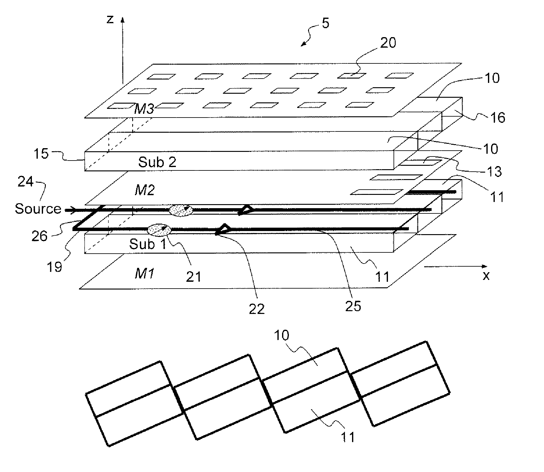
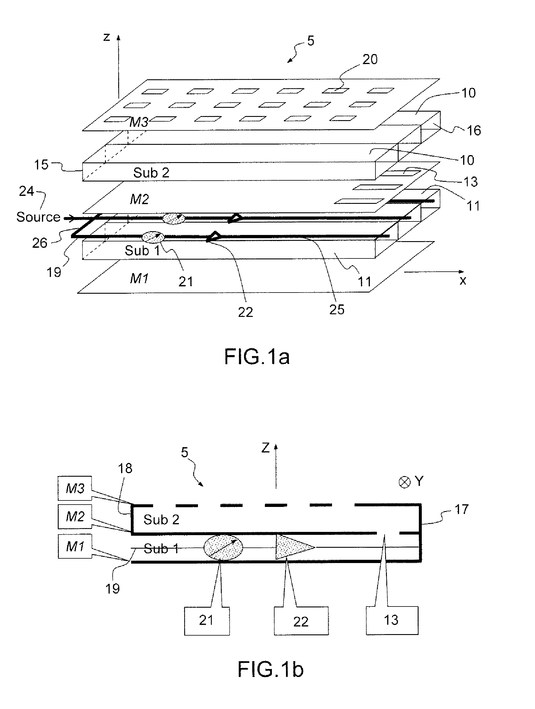
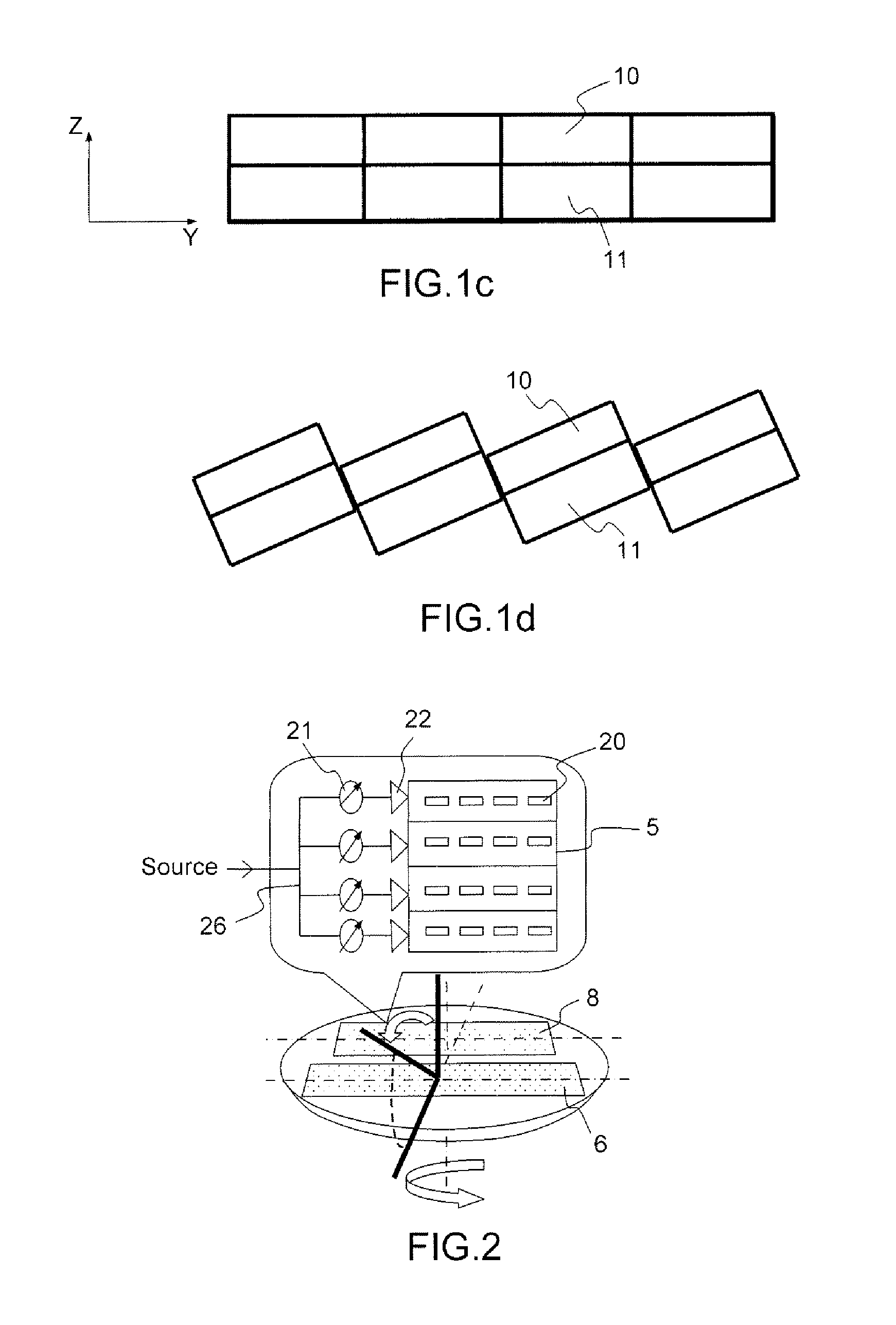
[0030]The flat antenna shown in FIGS. 1a, 1b and 1c comprises a slotted waveguide array 5 comprising two, respectively lower and upper, dielectric substrates Sub1, Sub2 which are superposed one above the other. The upper dielectric substrate Sub2 supports slotted waveguides 10, and the lower substrate Sub1 supports waveguides 11 intended for individually supplying each slotted waveguide 10 with a microwave signal. Three slotted waveguides are shown in FIG. 1a and four slotted waveguides are shown in FIGS. 1c and 1d, but these numbers are not limiting and may take any value equal to or greater than one. Preferably, the waveguides have a rectangular cross section. In the embodiment corresponding to FIGS. 1a, 1b, 1c, the planes of the various layers of the antenna are parallel to the XY plane and, in each substrate layer, the waveguides are placed beside one another, so as to be parallel to the XY plane. The upper and lower walls of all the waveguides are then formed by three metal pla...


PUM


Abstract

A flat scanning antenna comprises at least one slotted waveguide array comprising two dielectric substrates, one superposed above the other. The two substrates comprise the same number of waveguides, which are in mutual correspondence and communicate between them, pairwise, via corresponding coupling slots. Each waveguide of the upper substrate further includes a plurality of radiating slots, all the radiating slots being mutually parallel and oriented in the same direction and each waveguide of the lower substrate includes an individual internal supply circuit comprising an individual phase-shift/amplification electronic circuit.

Description

CROSS-REFERENCE TO RELATED APPLICATIONS[0001]This application is a National Stage of International patent application PCT / EP2011 / 050513, filed on Jan. 17, 2011, which claims priority to foreign French patent application No. FR 1000473, filed on Feb. 5, 2010, the disclosures of which are incorporated by reference in their entirety.FIELD OF THE INVENTION[0002]The present invention relates to a flat scanning antenna, to a vehicle having such an antenna and to a satellite telecommunication system comprising such a vehicle. It applies notably to the satellite telecommunications field and more particularly to telecommunication equipment onboard mobile vehicles, such as terrestrial, maritime or aeronautical transport means, for providing a two-way connection between a mobile terminal and an earth station via a repeater onboard a satellite.BACKGROUND[0003]In transport means such as trains and buses, there is an increasing requirement both for connections to a broadband Internet service and ...

Claims


Application Information

Patent Timeline
Patent Type & Authority Patents(United States)
IPC IPC(8): H01Q13/10H01Q3/00H01Q1/32H01Q3/04H01Q3/26H01Q21/00
CPCH01Q1/3275H01Q3/04H01Q3/26H01Q21/005
Inventor LENORMAND, REGISMEROUR, JEAN-MICHELMATEUS, JEAN-MICHELSAULEAU, RONANETTORRE, MAURORAGUENET, GERARD
Owner THALES SA
Why Eureka
Try Eureka