Optical grid enhancement for improved motor location

a technology of optical grid and motor location, which is applied in the direction of instruments, sensing record carriers, mountings, etc., can solve the problems of difficult to achieve even quarter grid positioning of the lens, difficult to discern focusing problems, and poor resolution of piezo motors, so as to improve the level of positional information and accurate positioning of the piezo motor

Active Publication Date: 2015-03-10
INTERMEC IP CORP
View PDF7 Cites 638 Cited by
  • Summary
  • Abstract
  • Description
  • Claims
  • Application Information

AI Technical Summary

Benefits of technology

[0009]In particular, embodiments of the present invention, computer-readable media is provided for, among other things, performing a scheme that results in a refined measurement pattern within an optical grid. Within conventional systems, physically adjusting spacing of elements within an optical grid to achieve minimal positional discrepancy is limited, as physical reduction of the spacing causes the light sensors of the optical grid to pick up interfering signals when reading light beams. In contrast, the technology introduced by the present invention generates a virtual reduced spacing of the elements within the optical grid using two signals that are physically offset from one another. These slightly offset signals can accomplish quarter-grid spacing resolution from any optical grid. The enhanced resolution derived from the virtual reduced spacing is then combined with an accurate characterization of movement of a piezo motor (e.g., using a novel motor movement algorithm), thereby allowing operation in a linear-motion phase of the motor during a critical portion of locating the lens.

Problems solved by technology

Further, some piezo motors offer poor resolution because they are limited by the wavelength of the light beams.
In the application of locating a lens quickly and accurately using these piezo motors, location errors smaller than the grid spacing cause discernable focusing problems with a barcode imager.
This sensor tolerance, coupled with non-linear movement of the piezo motor, rarely allow even quarter grid positioning of the lens to be achieved.
Within conventional systems, physically adjusting spacing of elements within an optical grid to achieve minimal positional discrepancy is limited, as physical reduction of the spacing causes the light sensors of the optical grid to pick up interfering signals when reading light beams.

Method used


Image

  • Optical grid enhancement for improved motor location
  • Optical grid enhancement for improved motor location
  • Optical grid enhancement for improved motor location

Examples


Embodiment Construction

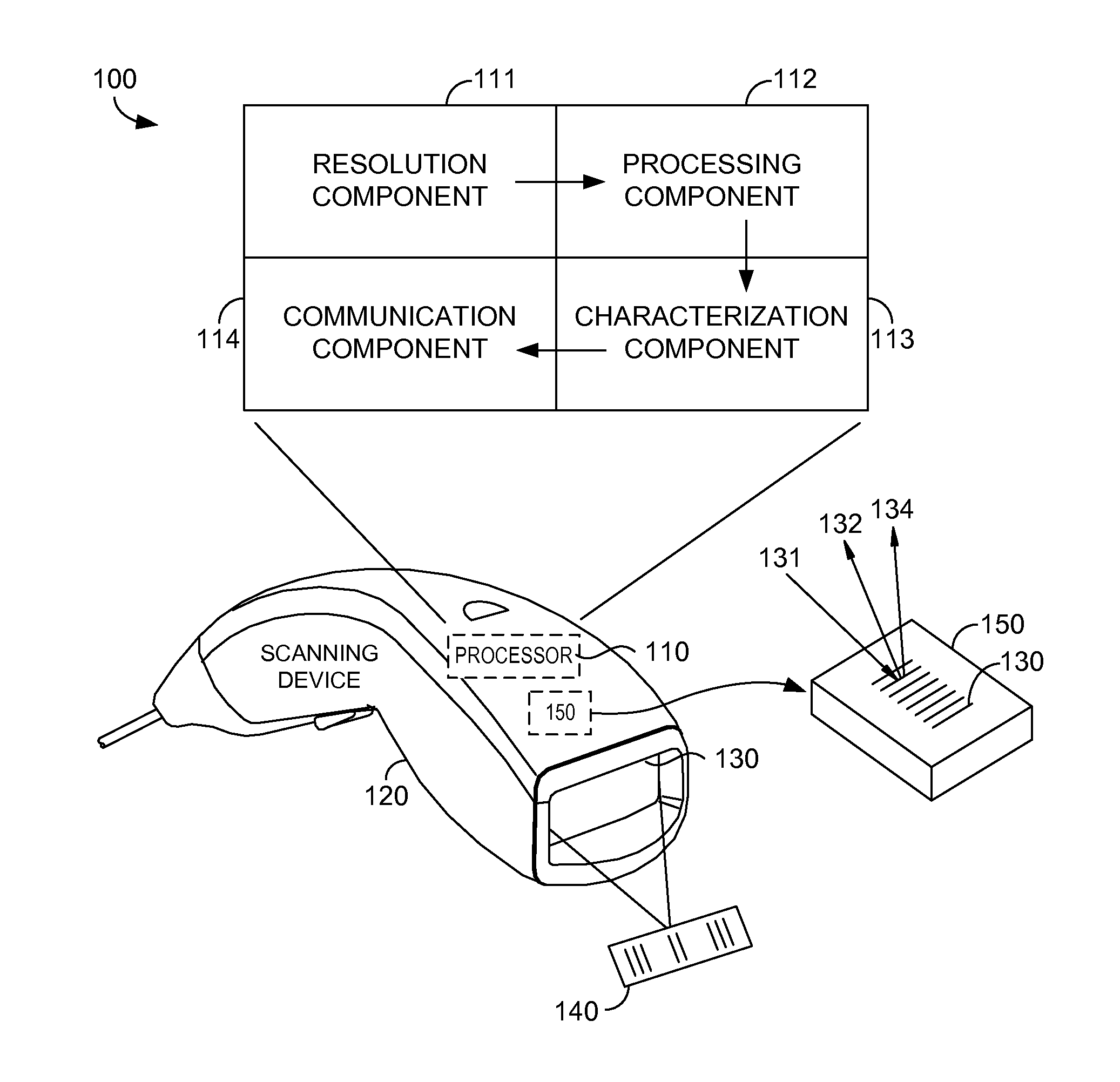
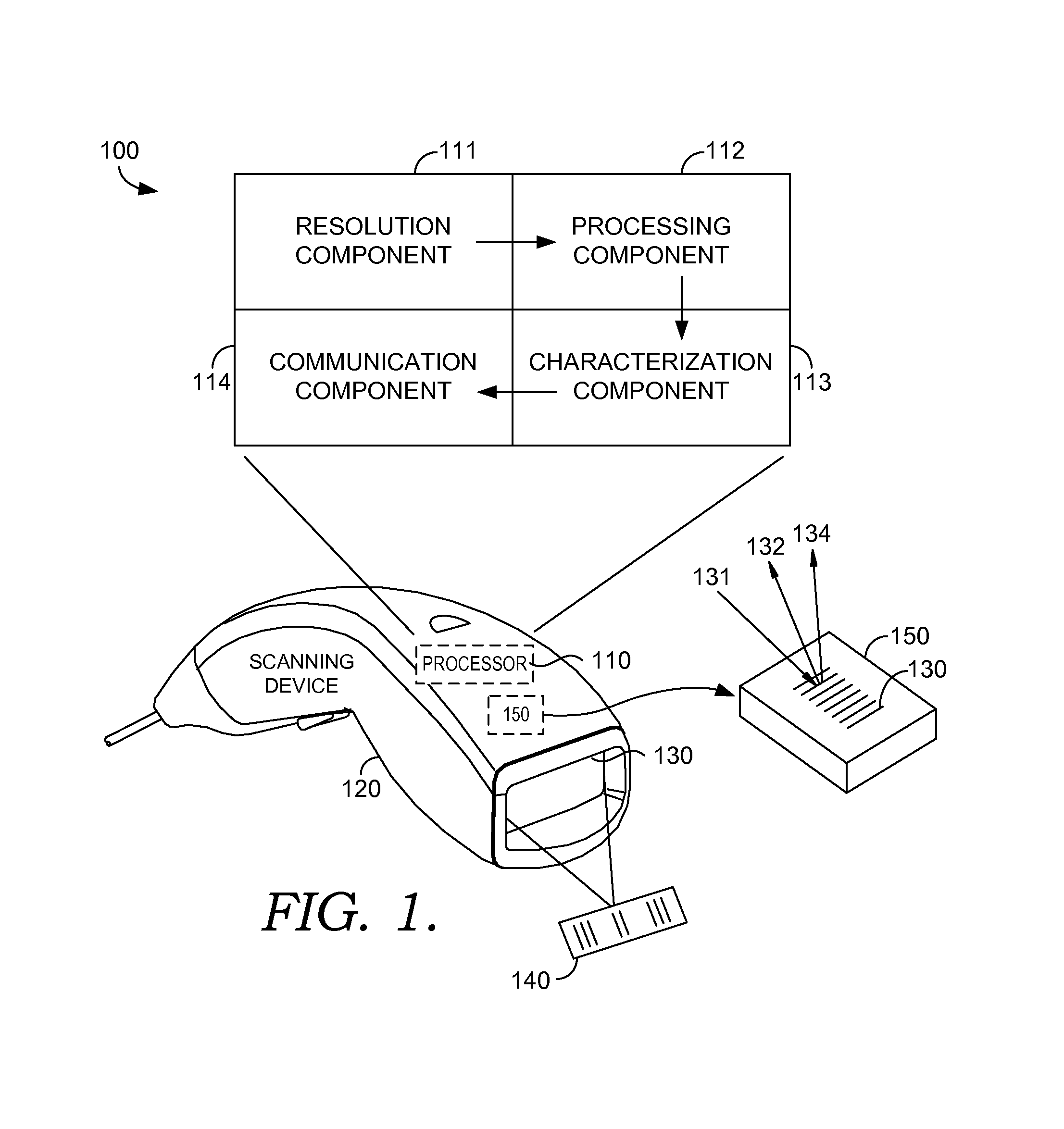
[0018]Embodiments provide media and methods for locating a physical object in relation to an optical grid using an innovative technique to achieve high resolution and programming a motor with a scheme that rapidly adjusts a physical object (e.g. a camera lens) to a precise and desired position. In other words, technology introduced herein relates to virtually reducing spacing of elements within an optical grid (achieving high resolution), and utilizing a motor to locate a physical object between the elements (employing the scheme).

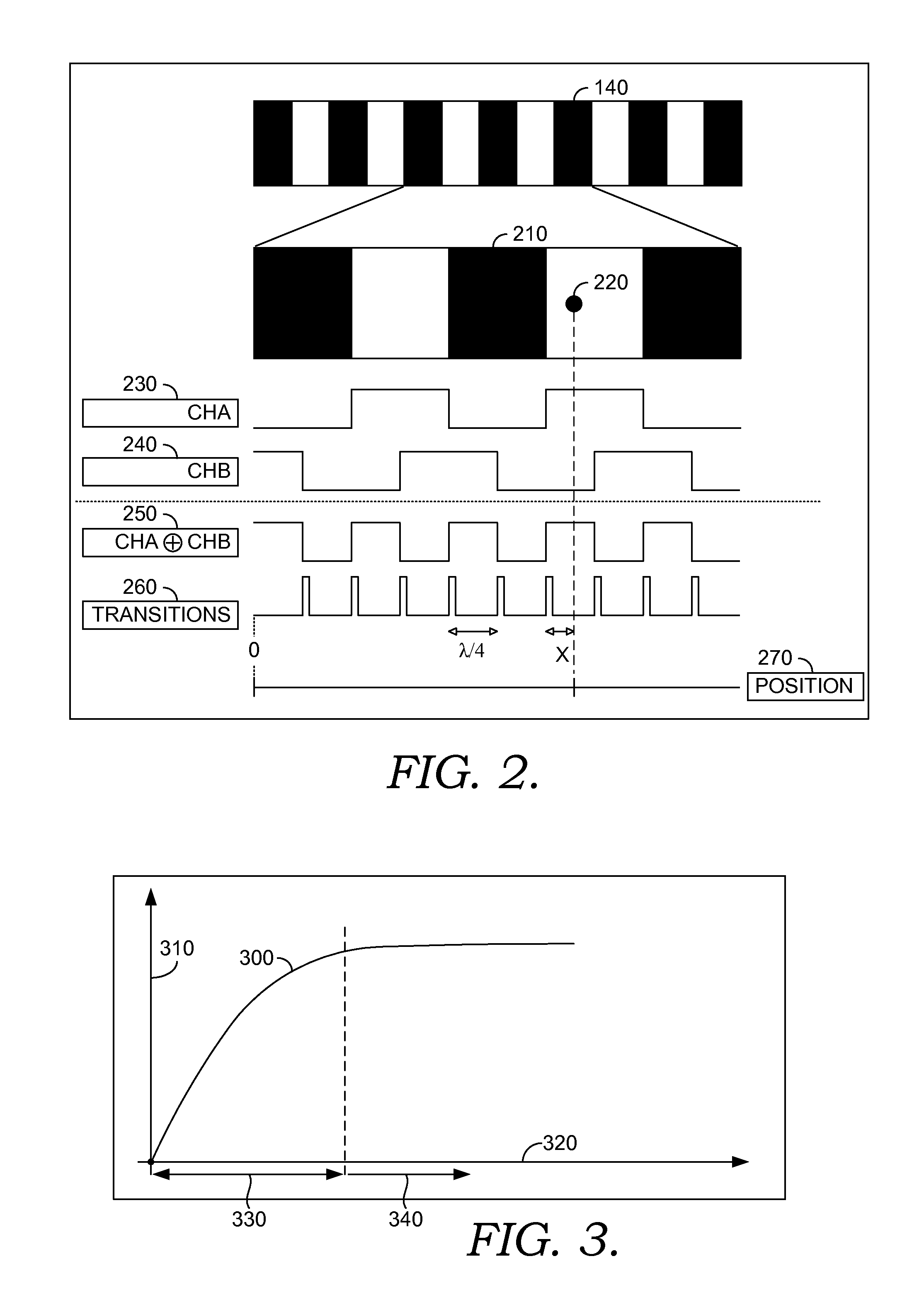
[0019]Initially, an exemplary method for virtually reducing spacing of elements within an optical grid includes the step of receiving input from a light sensor configured to read a first beam of light and a second sensor configured to read a first beam of light. Typically, the first beam of light is detected by a sensor that is spatially offset from the second sensor. Based on the input from the light sensors, software is provided to derive a pattern of tr...


PUM


Abstract

Methods for performing a scheme that results in a refined measurement pattern within an optical grid are provided. Physically adjusting spacing of elements within an optical grid to achieve enhanced resolution is historically unfeasible, as reduction of the spacing causes light sensors of the optical grid to pick up false signals when reading light beams. Technology introduced by the present invention generates a virtual reduced spacing of the elements within the optical grid by using two signals that are slightly different. These slightly different signals can accomplish, at least, quarter-grid spacing resolution within the optical grid. Additionally, the enhanced resolution derived from the virtual reduced spacing is employed to govern movement of a motor. The motor movement is in response to one or more changes of direction such that the motor is operating in its linear range. Advantageously, the virtual reduced spacing allows for substantial movement in a non-linear phase, while only limited movement in a linear phase is necessary to locate accurately a target within the optical grid.

Description

CROSS-REFERENCE TO RELATED APPLICATIONS[0001]This application claims the benefit of U.S. Provisional Application No. 61 / 535,007 filed Sep. 15, 2011, entitled “Optical Grid Enhancement for Improved Motor Location,” herein incorporated by reference.STATEMENT REGARDING FEDERALLY SPONSORED RESEARCH OR DEVELOPMENT[0002]Not applicable.BACKGROUND OF THE INVENTION[0003]This invention relates to a employing an optical grid to monitor and control movement of a device. More particularly, employing a processing unit to implement an improved scheme for sending and processing beams of light within an optical grid and using the output of the processing unit to control piezo movement of a motor is disclosed.[0004]Generally, off-the-shelf optical grids allow high measurement accuracy. As used herein, the phrase “optical grid” represents a linear arrangement of optical elements, where each optical element is located at a precise distance from the previous optical element. These optical elements may i...

Claims


Application Information

Patent Timeline
Patent Type & Authority Patents(United States)
IPC IPC(8): G01B11/14G01B11/16G01B11/28G01B11/25
CPCG01B11/14G01B11/25G01B11/28G01B11/167G01B11/16G02B7/09G06K7/10851
Inventor EL AKEL, KHALIDSTANG, JEAN-PIERRESERRES, BERNARD
Owner INTERMEC IP CORP
Why Eureka
Try Eureka