Fault diagnosis method and fault diagnosis device

a fault diagnosis and fault technology, applied in the field of fault diagnosis, can solve the problems of inconvenient process, worker is unable to sufficiently grasp the location of a specific displayed work process for the occurring faulty event within the entire required fault diagnosis procedure, and the purpose and meaning of the specific work process, so as to reduce the burden on the operator, improve the skill of the operator, and improve the effect of understanding

Active Publication Date: 2015-03-10
HONDA MOTOR CO LTD
View PDF20 Cites 4 Cited by
  • Summary
  • Abstract
  • Description
  • Claims
  • Application Information

AI Technical Summary

Benefits of technology

[0007]According to US2001 / 0002450A1, the worker merely is shown individual specific work content according to fault diagnosis procedures (see FIGS. 5A and 5B). Although the process allows even an inexperienced worker to easily carry out a fault diagnosis, the worker is unable to sufficiently grasp where a specific displayed work process for the occurring faulty event is located within the entire required fault diagnosis procedure, as well as the purpose and meaning of the specific work process. As a result, there is room for improvement as to the promotion of adequate decisions to be made by the worker, as well as sharpening the skills of the worker.
[0020]The work guidance step may comprise displaying the vehicle data together with judging criteria with respect to the vehicle data. Therefore, the operator can proceed with a specific work item after making a judgment in relation to the actual vehicle data and the judging criteria. It is thus possible to allow the operator to acquire a deeper understanding of the fault diagnosis, and for the skill of the operator to be sharpened.

Problems solved by technology

The process is inconvenient because it is tedious and time consuming for the worker to refer to the diagnostic procedures and normal value data in the service manual.
Although the process allows even an inexperienced worker to easily carry out a fault diagnosis, the worker is unable to sufficiently grasp where a specific displayed work process for the occurring faulty event is located within the entire required fault diagnosis procedure, as well as the purpose and meaning of the specific work process.

Method used


Image

  • Fault diagnosis method and fault diagnosis device
  • Fault diagnosis method and fault diagnosis device
  • Fault diagnosis method and fault diagnosis device

Examples


embodiment

A. Embodiment

1. Arrangement

(1) Overall Arrangement:

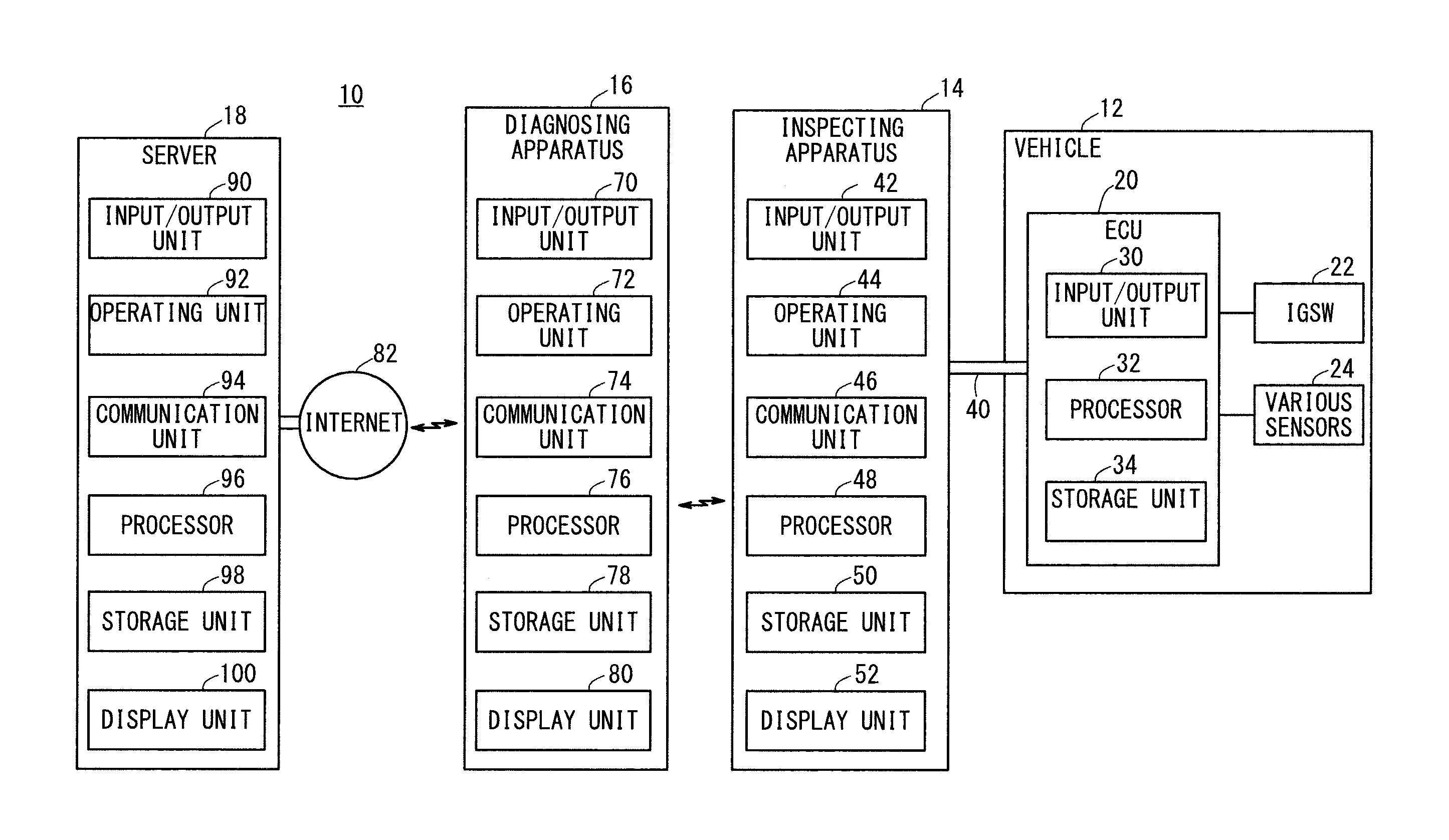
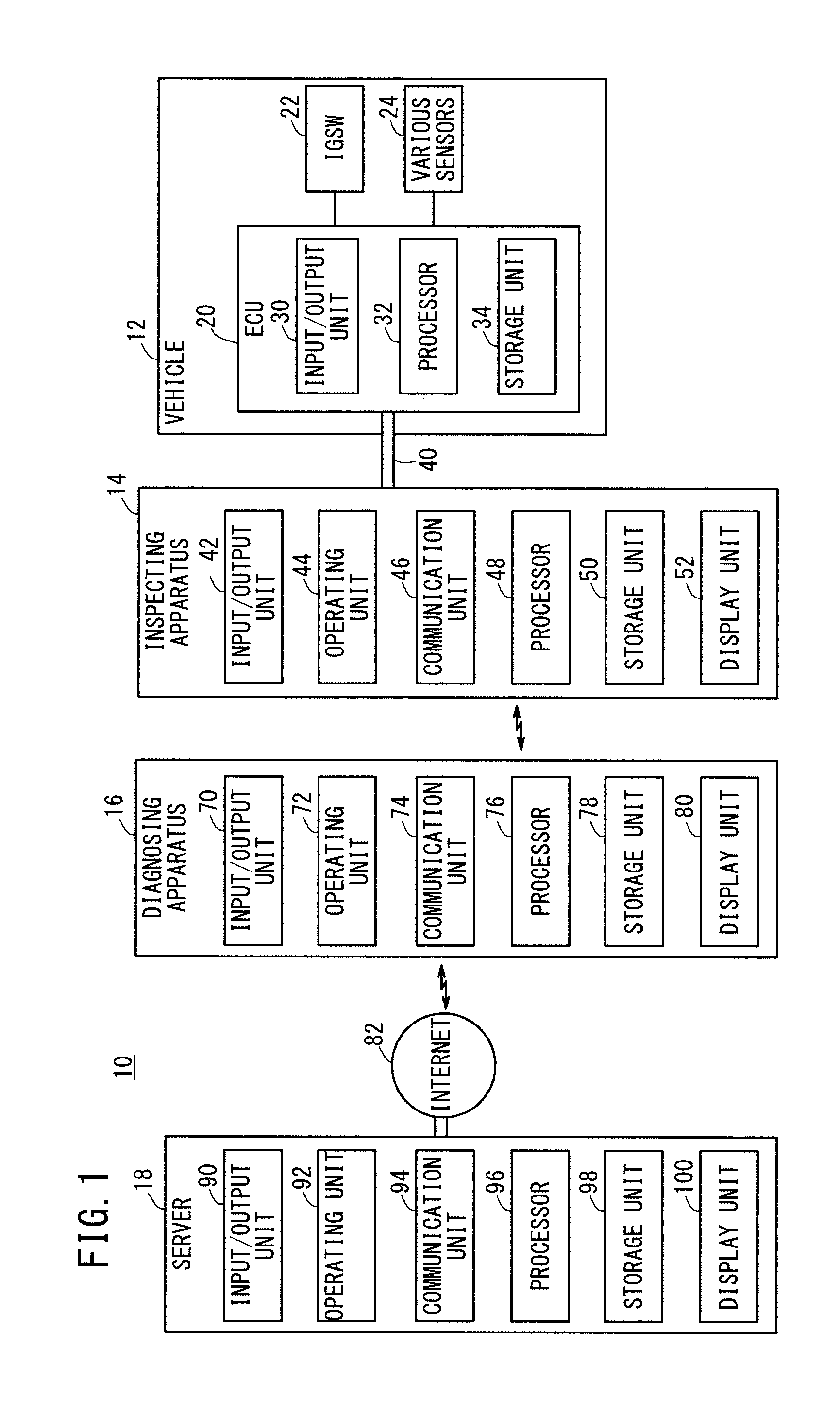
[0041]FIG. 1 is a block diagram showing a general arrangement of a fault diagnosing system 10 (hereinafter also referred to as a “system 10”) incorporating a fault diagnosing apparatus 16 (hereinafter referred to as a “diagnosing apparatus 16”) according to an embodiment of the present invention. The system 10 includes a vehicle 12 as a target object to be diagnosed, an inspecting apparatus 14 serving as an interface for reading out from the vehicle 12 self-diagnosed data concerning the vehicle 12, a diagnosing apparatus 16 for diagnosing the vehicle 12 for a fault, and a server 18. In FIG. 1, the vehicle 12, the inspecting apparatus 14, and the diagnosing apparatus 16 are shown individually each consisting of one device. However, the vehicle 12, the inspecting apparatus 14, and the diagnosing apparatus 16 may each be made up from a plurality of devices.

(2) Vehicle 12:

[0042]The vehicle 12 has an electronic control unit 20 (hereinaft...


PUM


Abstract

A fault diagnosis device and a fault diagnosis method read a diagnostic trouble code from an Electronic Control Unit to the fault diagnosis device, and display a work guide screen for guiding work in accordance with the read diagnostic trouble code. The work guide screen includes an entire work flowchart consisting of a plurality of work items for identifying a fault occurrence location at which the fault event corresponding to the diagnostic trouble code is caused, and includes an entire work display area in which a work item selected among the plurality of work items is highlighted and a concrete work display area in which concrete work details about the highlighted work item are indicated.

Description

TECHNICAL FIELD[0001]The present invention relates to a fault diagnosing method (fault diagnosis method) and a fault diagnosing apparatus (fault diagnosis device) connected to an electronic control unit mounted on a vehicle, for reading self-diagnosis result data stored in the electronic control unit into an external diagnosing apparatus, which serves as the fault diagnosing apparatus for diagnosing the vehicle for a fault. More particularly, the present invention relates to a fault diagnosing method and a fault diagnosing apparatus for performing a diagnostic process according to a fault diagnosing procedure displayed on a monitor screen.BACKGROUND ART[0002]When a fault occurs in the control system (electronic control unit (ECU), various sensors, etc.) of a vehicle, the driver recognizes the fault based on the occurrence of an abnormal symptom, lighting of a warning lamp, or the like, and brings the vehicle to a dealer or a repair shop.[0003]The worker (technician) who is in charge...

Claims


Application Information

Patent Timeline
Patent Type & Authority Patents(United States)
IPC IPC(8): G01M17/00G06F7/00G06F19/00G06F17/00G07C5/00G07C5/08
CPCG06F17/00G07C5/0816G07C5/008G07C2205/02
Inventor ISHIMARU, KENJIOKABE, YUDAIITO, HIROSHIOKAZAKI, KUSUO
Owner HONDA MOTOR CO LTD
Why Eureka
Try Eureka