Computer system
a computer system and computer technology, applied in computing, instruments, electric digital data processing, etc., can solve problems such as cost increase, and achieve the effect of suppressing the decrease in flexibility or extensibility of a computer system
- Summary
- Abstract
- Description
- Claims
- Application Information
AI Technical Summary
Benefits of technology
Problems solved by technology
Method used
Image
Examples
embodiment 1
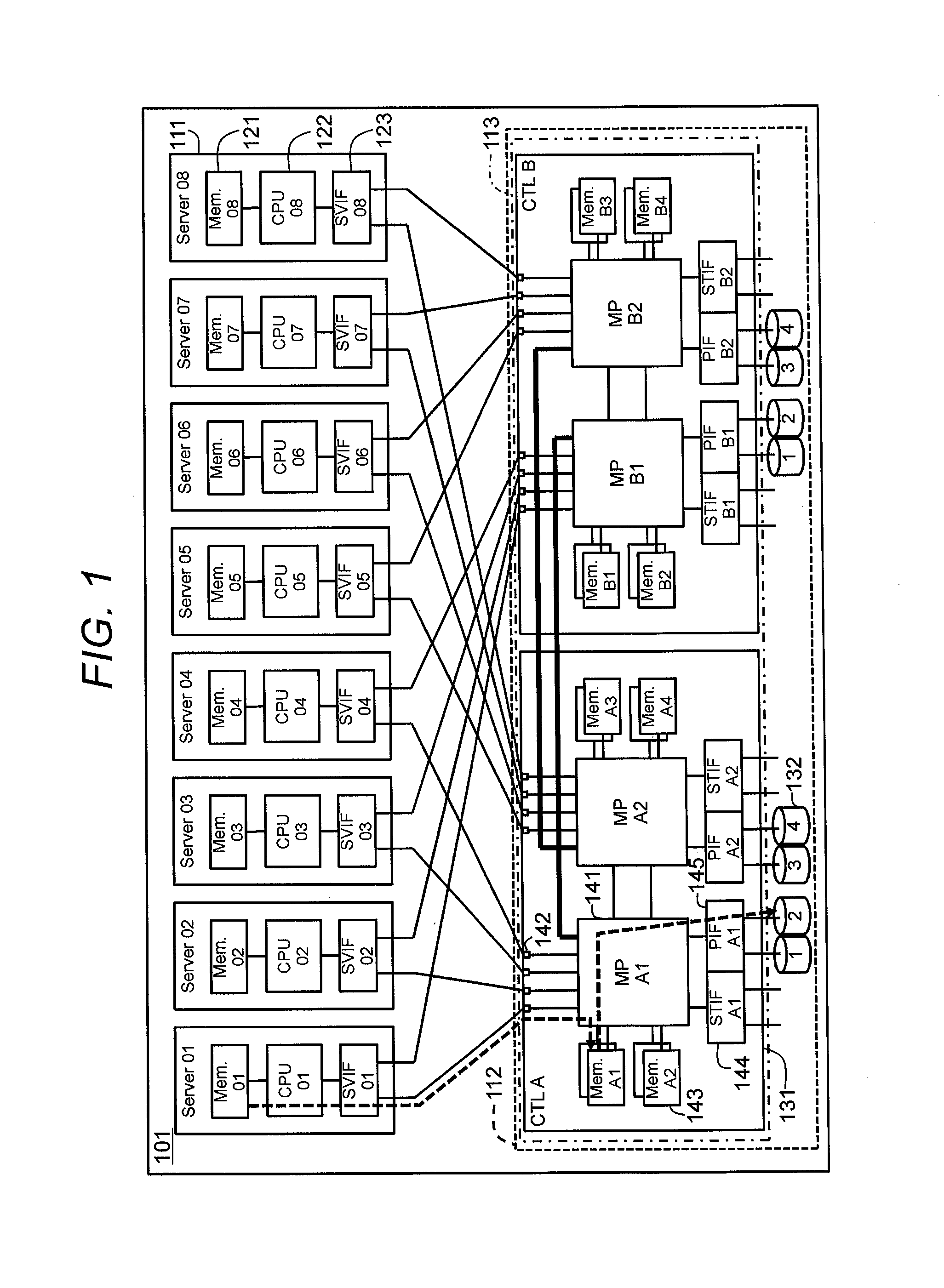
[0029]FIG. 1 is a diagram illustrating a computer system according to Embodiment 1.
[0030]First, the outline of Embodiment 1 will be described below.
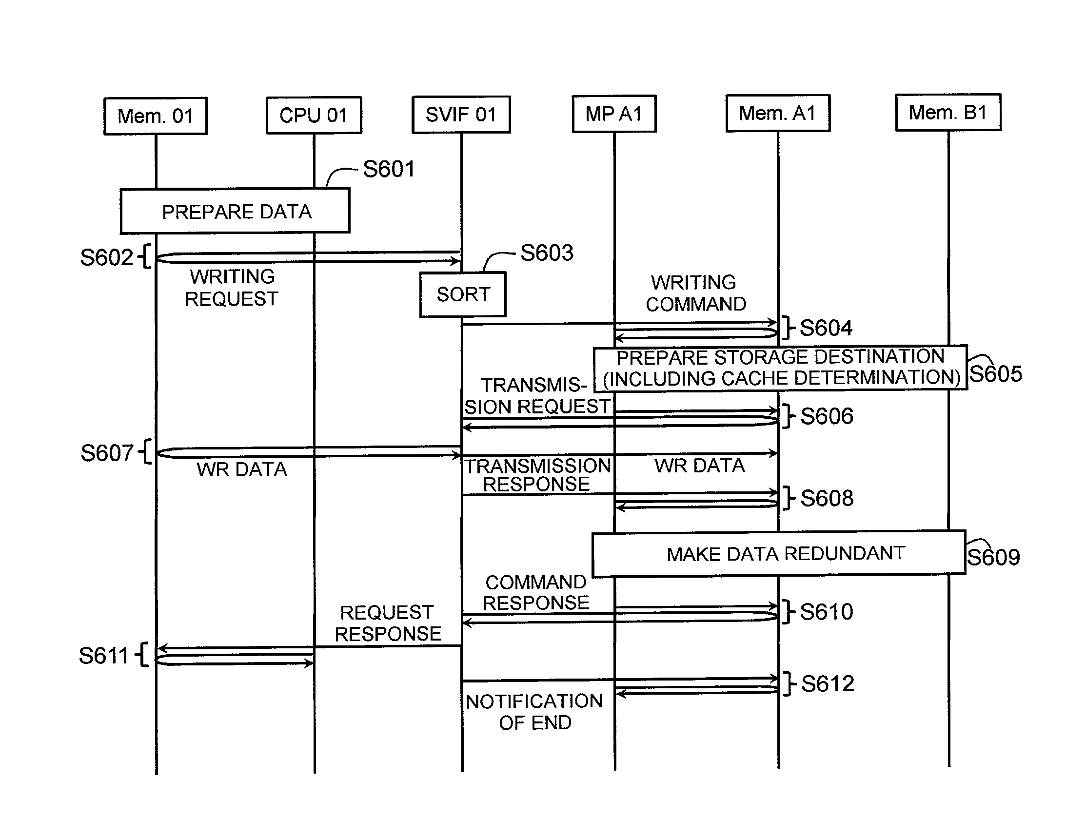
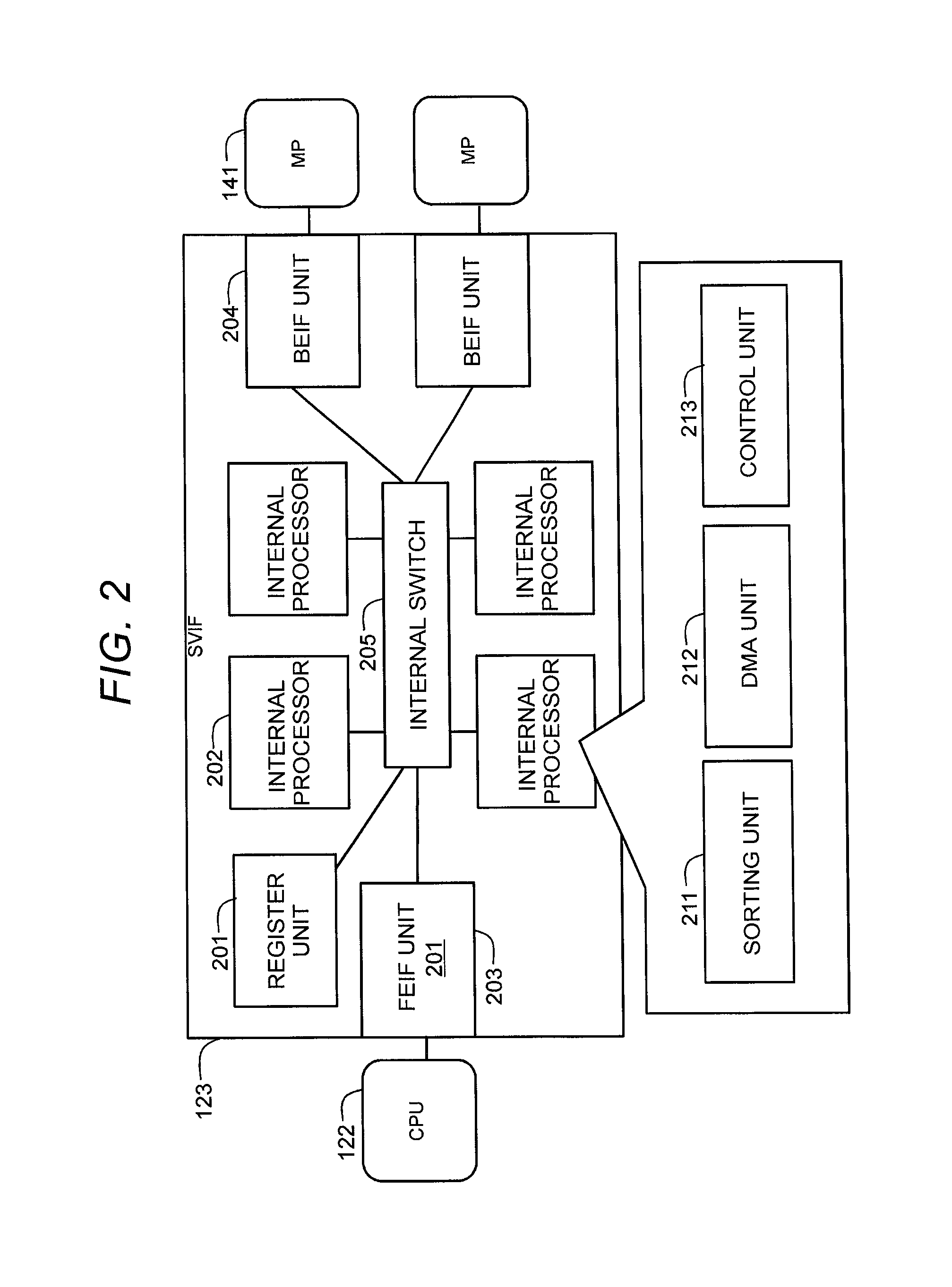
[0031]A computer system includes a server module (hereinafter, referred to as a server) 111 and a storage control module 113 connected to the server 111 via a bus. In this embodiment, plural server modules are provided and all of them are connected to the storage control module. The storage control module 113 includes plural microprocessors (MP) 141. The plural servers 111 are connected to plural controllers 131 of the storage control module 113, respectively, and each server 111 may have a path to one controller 131 (for example, CTL A) and a redundant path to another controller 131 (for example, CTL B). Each server 111 includes a central processing unit (CPU) 122 issuing an input / output (I / O) request and a server I / F (hereinafter, referred to as an SVIF) 123 which is a communication interface circuit. The SVIF 123 specifies a target MP...
embodiment 2
[0085]Hereinafter, Embodiment 2 will be described. Here, differences from Embodiment 1 will be mainly described and common points to Embodiment 1 will not be described or will be described in brief.
[0086]In Embodiment 2, the storage 112 (storage control module 113) is scaled out. Specifically, K storage control modules 113 are connected in series (in multiple stages) and the first storage control module 113 of the K storage control modules 113 can be connected to N servers 111 (where N is an integer of 2 or more, for example, N=8). For example, P chasses 101 (where P is an integer of 2 or more) may be provided and each chassis 101 may include at least one storage control module. By connecting the STIFs 144 to each other, the K storage control modules 113 in the P chasses 101 can be connected in series (in multiple stages).
[0087]While K=1 (and P=1) is set in Embodiment 1, K may be an integer of 2 or more and K=2 is set in Embodiment 2. Embodiment 2 will be described below in detail. ...
embodiment 3
[0110]Hereinafter, Embodiment 3 will be described. Here, differences from Embodiments 1 and 2 will be mainly described and common points to Embodiments 1 and 2 will not be described or will be described in brief.
[0111]In Embodiment 3, the servers 111 are scaled out (the storages may also be scaled out as described in Embodiment 2). Specifically, Q servers 111 (where Q is an integer of 1 or greater) in addition to N servers 111 (N=8 in Embodiments 1 and 2) are connected to a storage control modules. The (N+Q) servers 111 are connected to the storage control module via plural port extension modules. Regarding the port extension module, for example, since 16 PCIe×4s are drawn out from the storage, 12 ports are switched to be drawn out for different chasses and the remaining four ports support the original eight servers. 12 ports drawn out for different chasses are connected to three chasses by four ports and the eight servers of each chassis use the four ports. In FIG. 13, two PCIe×4s ...
PUM
 Abstract
Description
Claims
Application Information
 - R&D
- Intellectual Property
- Life Sciences
- Materials
- Tech Scout
- Unparalleled Data Quality
- Higher Quality Content
- 60% Fewer Hallucinations
Browse by: Latest US Patents, China's latest patents, Technical Efficacy Thesaurus, Application Domain, Technology Topic, Popular Technical Reports.
© 2025 PatSnap. All rights reserved.Legal|Privacy policy|Modern Slavery Act Transparency Statement|Sitemap|About US| Contact US: help@patsnap.com


