Energy-saving valve

a valve and energy saving technology, applied in the field of valves, can solve the problems of increasing the initial cost, complicated equipment, increasing the complexity, etc., and achieve the effects of saving air consumption, reducing pressure, and saving energy

Active Publication Date: 2015-03-17
SMC CORP
View PDF16 Cites 12 Cited by
  • Summary
  • Abstract
  • Description
  • Claims
  • Application Information

AI Technical Summary

Benefits of technology

[0008]It is an object of the present invention to provide an energy-saving valve which can save air consumption and impart a simple structure and a small size to equipment with the result that the initial cost and running cost of the equipment can be reduced.
[0009]It is another object of the present invention to provide a valve with a more simple structure and a smaller size as compared with the above valve.
[0015]In the above energy-saving valve according to an aspect of the present invention, a mechanism to reduce the pressure of supplied compressed air in a return stroke which does not require large driving force is integrated with the main valve, which enables energy conservation by saving air consumption and enables simplification and downsizing of equipment. The running cost and initial cost of the equipment can be accordingly reduced.

Problems solved by technology

However, since the pressure-reducing valves 6 and 125 need to be provided in addition to a valve which enables air to be selectively supplied into and discharged from the pressure action chambers of the cylinder tube, equipment becomes complicated and large, which leads to the increase of the initial cost.

Method used


Image

  • Energy-saving valve
  • Energy-saving valve
  • Energy-saving valve

Examples


Embodiment Construction

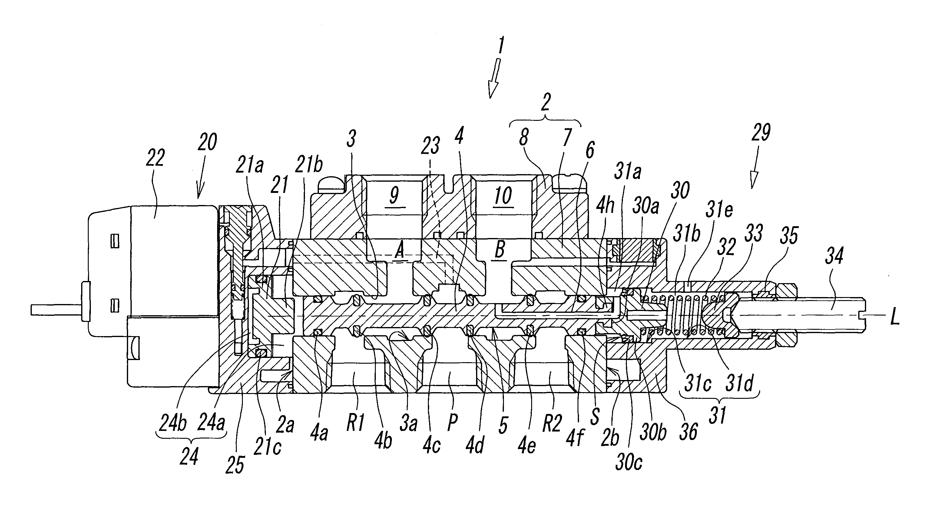
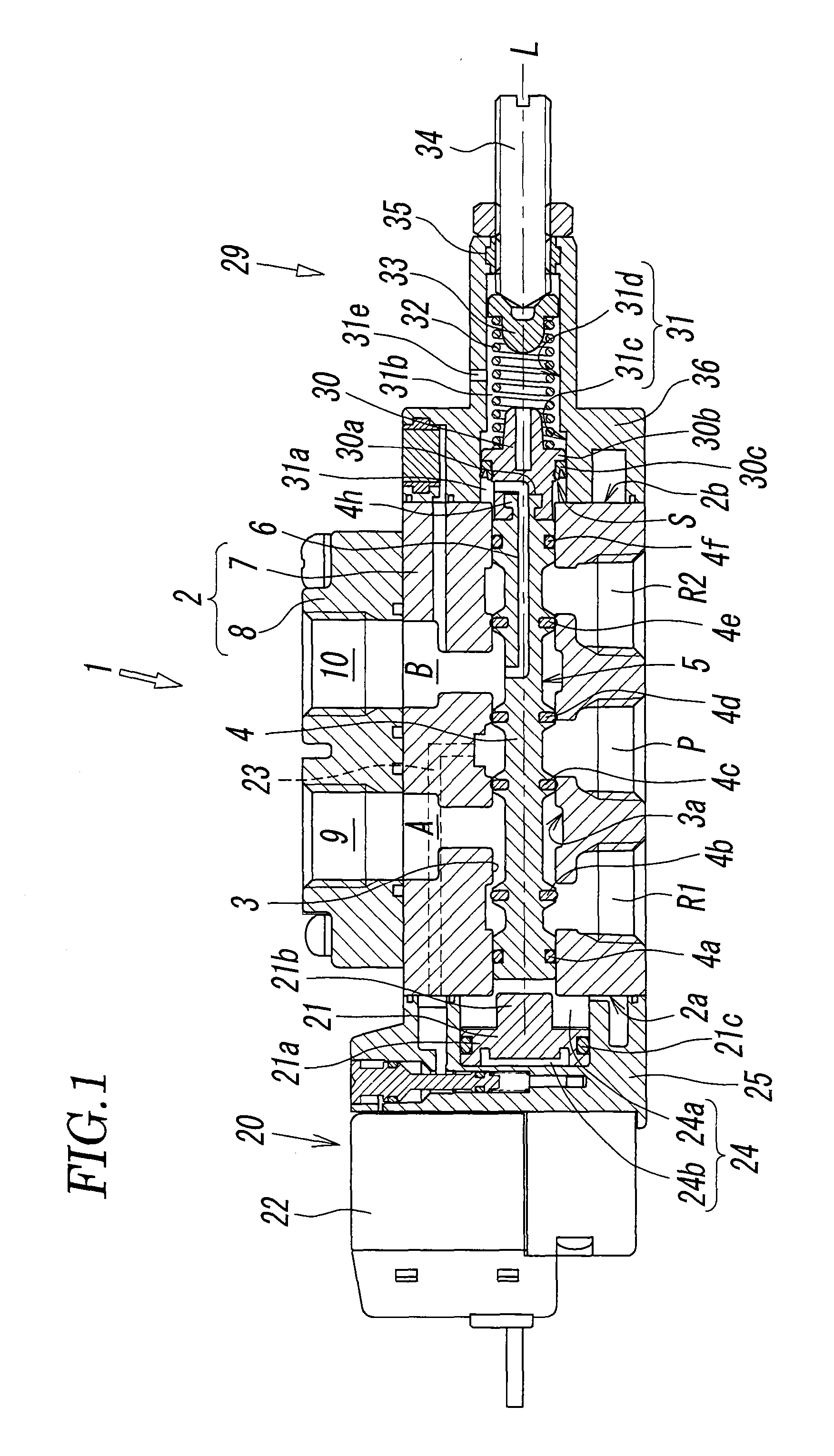
[0022]FIG. 1 illustrates the configuration of an energy-saving valve of the present invention (hereinafter simply referred to as “valve”). A main valve body 2 of a valve 1 generally includes one valve hole 3 which penetrates the inside of a valve casing 7 of the valve main body 2 so as to extend from a first end 2a to a second end 2b opposite thereto in a direction of an axis L; a series of a first air-discharging port R1, an air-supplying port P, and a second air-discharging port R2 which are provided in sequence from the first end 2a to the second end 2b, each having one end which is in communication with the valve hole 3 and having the other end which opens toward one side (lower surface) of the main vale body 2 in parallel with the valve hole 3; and a first output port A and a second output port B, each having one end which is in communication with the valve hole 3 and having the other end which opens toward the other side (upper surface) of the main valve body 2, and the other ...


PUM


Abstract

An energy-saving valve includes a spool-driving unit which changes the position of a spool to a position at which compressed air is discharged from a first output port without pressure control and includes a pressure control unit which changes the position of the spool to a position at which compressed air is discharged from a second output port in a predetermined pressure level due to pressure control. The pressure control unit includes a pressure control piston, a pressure-receiving surface which enables air pressure in the second output port to act on the pressure control piston, a cylinder chamber, a pressure control channel, and an elastic member which applies biasing force to the pressure control piston in a direction opposite to the action of air pressure on the pressure-receiving surface to determine pressure.

Description

BACKGROUND OF THE INVENTION[0001]1. Field of the Invention[0002]The present invention relates to a valve having a mechanism to enable change between supply and discharge of air, in particular, relates to an energy-saving valve having a decompression mechanism which enables the pressure of compressed air to be reduced and the compressed air to be discharged from a discharging port.[0003]2. Description of the Related Art[0004]In typical air cylinders which have been widely used as pneumatic actuators in various types of automatic machines, a piston having a fixed rod reciprocates in a process in which compressed air is supplied into a pressure chamber and the compressed air is then discharged from the pressure chamber. In general, air is supplied to and discharged from air cylinders by a diverter valve.[0005]In such air cylinders, although a working stroke which contributes to works in the reciprocation of a piston needs large driving force because external loads are imposed on a rod ...

Claims


Application Information

Patent Timeline
Patent Type & Authority Patents(United States)
IPC IPC(8): F15B13/043F16K11/02F16K11/044
CPCF16K11/044F16K11/02F16K11/0716F15B11/064F15B13/0402F15B13/0417Y10T137/8671Y10T137/2597Y10T137/86614F16K31/36F16K11/07
Inventor MIYAZOE, SHINJISENBA, KATSUYUKIMURAKAMI, TAKASHI
Owner SMC CORP
Why Eureka
Try Eureka