Surgical guide device

a guide device and surgical technology, applied in the field of surgical guide devices, can solve the problems of small angle range, unsatisfactory positioning of fixing devices, and non-ideal healing strength of repaired bones, so as to improve the spacing of limbs, prevent tissue pinching, and improve the line of vision

Active Publication Date: 2015-03-17
CLEAR SURGICAL
View PDF18 Cites 9 Cited by
  • Summary
  • Abstract
  • Description
  • Claims
  • Application Information

AI Technical Summary

Benefits of technology

[0060]According to a preferred set of embodiments, the limbs, or at least one of the limbs, is optionally at least partially curved to accommodate one or more body portions between them. This may make it easier for the guide sleeve(s) to be suitably manipulated into place around a body portion e.g. bone fragment to be pinned within a body. The curved portion(s) of the limb(s) may also provide an X-ray beam path to reach the fracture site without interference, thereby enabling the fracture to be imaged during the reduction and fixing process. The curved portion(s) of the limb(s) can optionally lie in the same plane as the limb(s), or in more than one plane.
[0061]In one set of embodiments at least one of the limbs, preferably both the first and second limbs, of the device is curved or bent in the plane (e.g. x-y plane) of the limb(s). Optionally this is the main plane of the device as a whole, although in some embodiments there may be other parts of the device, such as finger loops, that extend out of the main x-y plane. Where the guide sleeve meets the other limb, or where the two guide sleeves meet, there can be defined an orthogonal plane (e.g. z plane) relative to the axis of the guide sleeve(s). Preferably the or each limb is curved or bent in the x-y plane of the limbs so as to increase the spacing of the limb(s) from this z-plane. Such a curve or bend in the limb(s) helps to prevent pinching of tissue between the bone portion held between the limbs and the rest of the device. It can also improve the line of vision for the surgeon and also for x-ray beams which are used to confirm that a fixing is in the correct position and that the bone has been aligned as required. The curved or bent portions of the limb(s) can therefore prevent the device from restricting the line of vision.
[0062]In one set of embodiments at least one of the limbs, preferably both the first and second limbs, of the device is curved or bent in a plane (e.g. z plane) that is out of the plane (e.g. x-y plane) of the limb(s). Such a z-plane may be at angle θ (0<θ<90° to the x-y plane or substantially orthogonal to the x-y plane. As is described above, such a curve or bend in the limb(s) can prevent the device from restricting the line of vision.

Problems solved by technology

However, since the ideal fixation site is typically blocked by the reduction device, the surgeon often has to insert the fixation device in a less than ideal position next to the reduction device.
This may ultimately lead to the possibility of non-ideal healing and strength of the repaired bone.
A problem with such scissor-type devices is that there is only a small range of angles between the two limbs of the device for which the longitudinal axis of the drill guide points directly at the opposite tip of the other limb of the scissor.
Accordingly such devices can only be used for a particular bone diameter and multiple devices will be required to accommodate different bones sizes.
For example, if such a device were to be used to clamp a larger bone diameter that that for which it is designed, the longitudinal axis of the drill guide would point beyond the tip of the other limb of the scissor, which would lead to non-ideal conditions for reducing, drilling and pinning the bone due to instability of the device clamped on the bone fragments.

Method used


Image

  • Surgical guide device
  • Surgical guide device
  • Surgical guide device

Examples


second embodiment

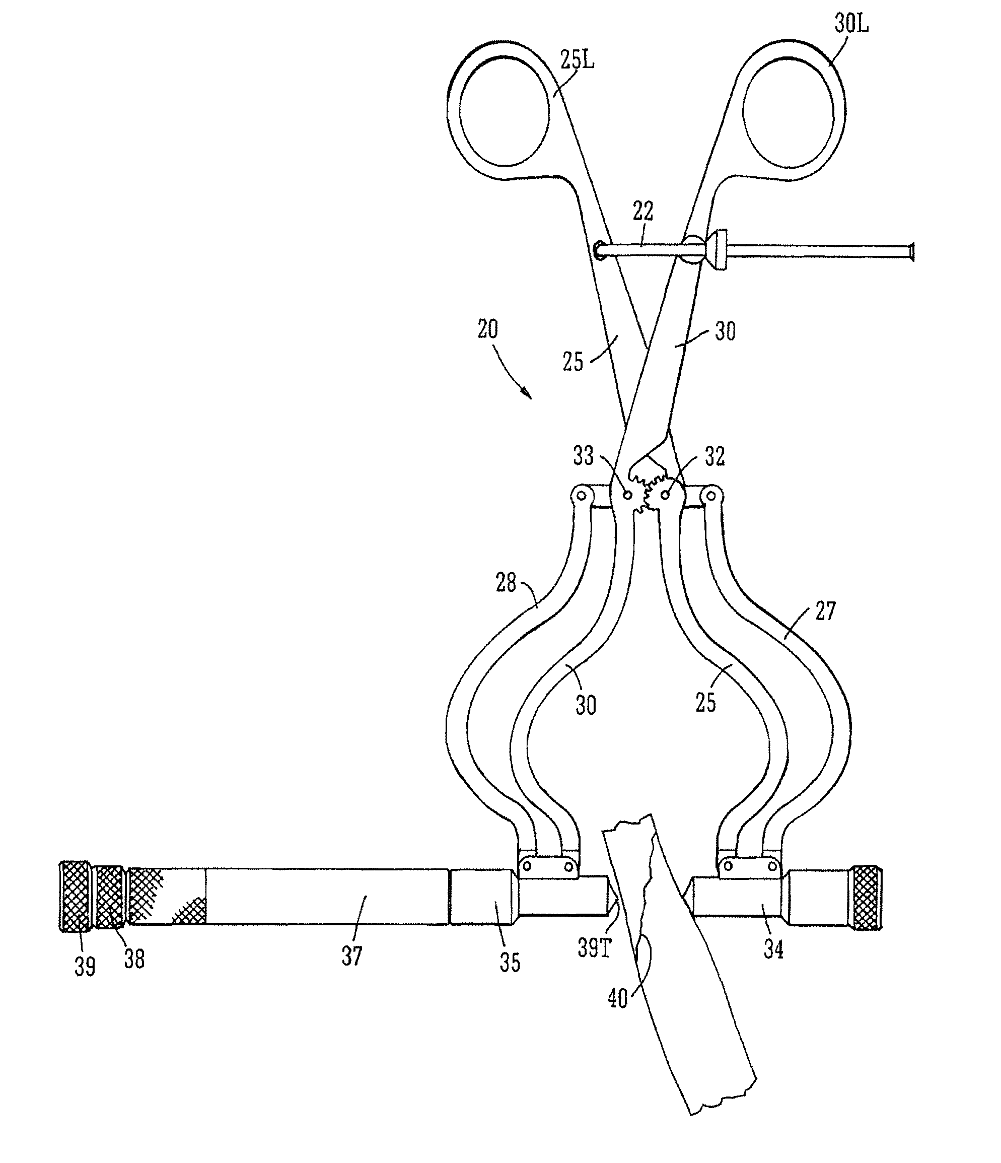
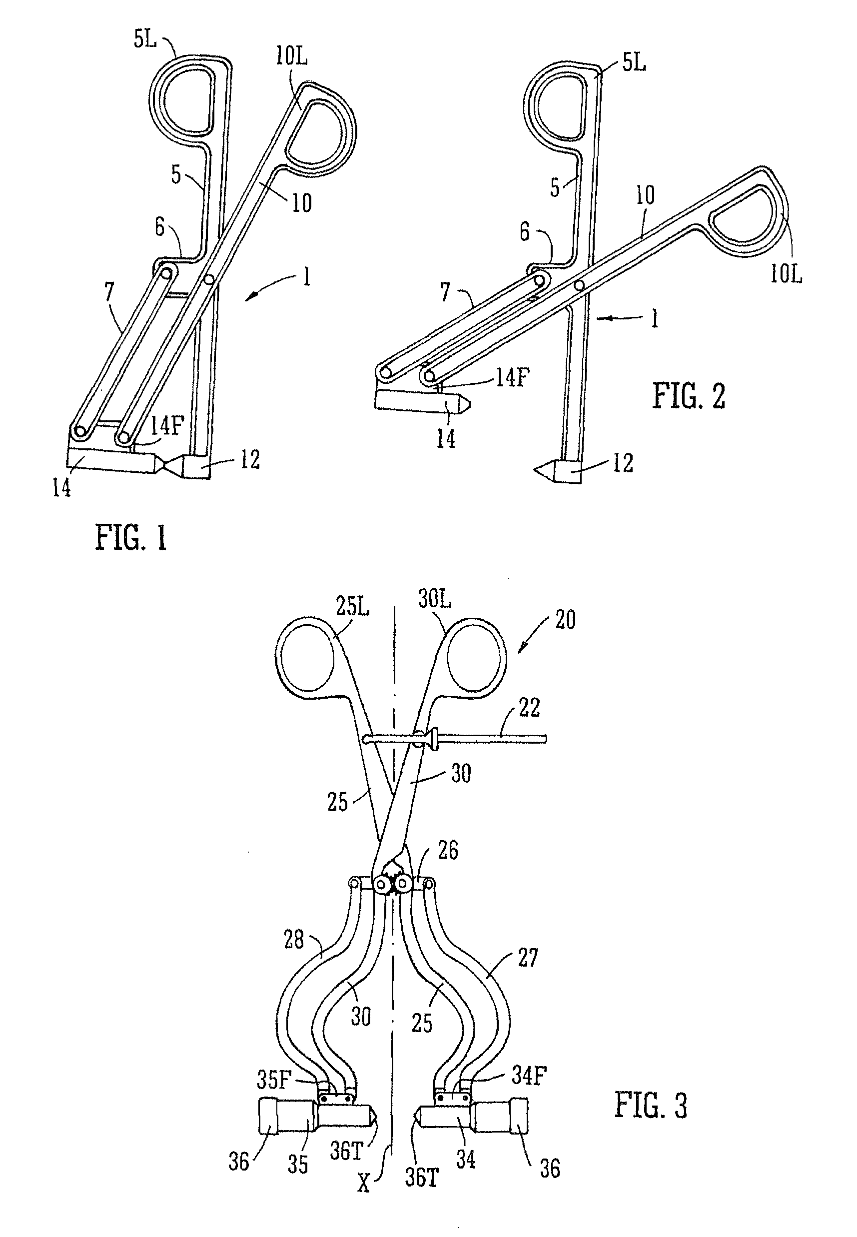
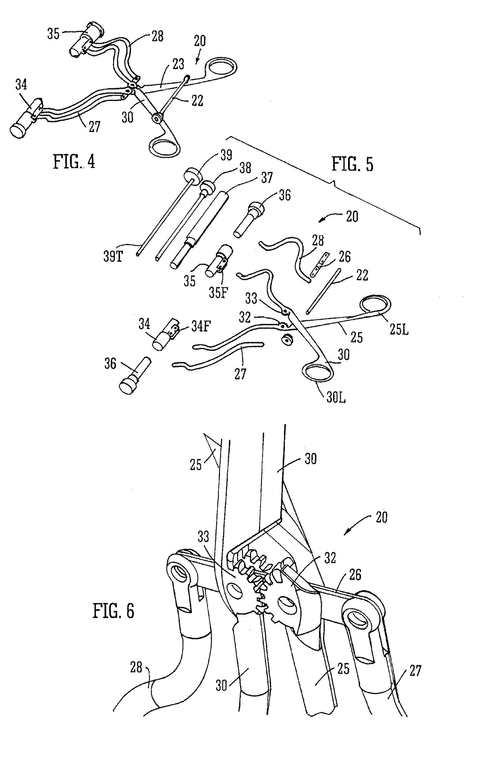
[0087]the device 20 has a respective orientation control bar 27, 28 for each limb 25, 30. As can best be seen in FIG. 6, the control bars 27, 28 are connected to the limbs 25, 30 by means of the yoke 26. The yoke 26 is pivotally connected to each of the limbs 25, 30, and to each of the control bars 27, 28 through pivot pins such as rivets or bolts or such like. The heads of the bars 27, 28, and optionally the limbs 25, 30 can be slotted to receive and retain the yoke 26 within the slot.

[0088]Optionally, the relative movement of the limbs 25, 30 and the yoke 26 around the pivot points is controlled by inter-meshing toothed members in this embodiment in the form of disc gears 32, 33, mounted respectively on limbs 25 and 30. In this embodiment, the gears 32, 33 are of similar diameter, and can be mounted on bolts extending through the pivot points between the limbs 25, 30 and the yoke 26, so that relative pivotal movement of one of the limbs (e.g. 25) initiates and controls the movemen...

third embodiment

[0101]In the third embodiment, the guide sleeves 64, 65 are typically non-identical, one of them 64 being shorter than the other 65. The shorter guide sleeve 64 can be used to access smaller spaces within the body to allow the clamp 50 to be placed appropriately around a fracture to be clamped. The smaller guide sleeve 64 can optionally accommodate a pin (not shown, but similar to pin 36) to retain the shorter sleeve on a bone surface during clamping. The longer guide sleeve 65 can be used to accommodate different sizes of insert with different diameters of bore, so that the drill can be properly supported within the bore of the guide sleeve 65 during drilling. Note that only one guide sleeve 65 is necessary in the present embodiment, and the guide sleeve 64, containing the pin, can optionally be changed for a solid pin without a sleeve, which can typically be adapted to pivot to remain in the same orientation during closing of the limbs.

[0102]In use, the guide device 50 according t...

fourth embodiment

[0108]The device 70 of the fourth embodiment has a different form of yoke 76. The yoke 76 has an inverted T shape, with a main bar 76A being retained parallel to the guide sleeves 84 by means of the orientation mechanism, a bar extension 76B slotted at 76C with a linear slot to receive a rivet 76R connecting link arms 79, which are pivotally connected together at the rivet 76R intersecting the slot 76C. The arms 79 are also pivotally connected to the limbs 75 and 80 between the loops 75L, 80L and the yoke 76.

[0109]In use, the device 70 according to the fourth embodiment is opened to the configuration shown in FIG. 14 typically to an extent sufficient to permit it to be placed around the fracture to be clamped. The handles of the limbs 75, 80 are pressed together to close the guide sleeves 84, 85 around the fracture.

[0110]Instead of using gears to coordinate the separation of the limbs 75, 80, the device 70 of the fourth embodiment uses the link arms 79, while the orientation bars 78...


PUM


Abstract

A surgical guide device comprises first and second limbs pivotally connected together, with a respective guide sleeve pivotally attached to each limb. Each guide sleeve has a bore through the sleeve that can guide a drill bit or bone fixing for insertion into a fragmented bone portion. The device has an orientation mechanism adapted to change the orientation of the guide sleeves relative to the limbs as the limbs move relative to one another, so as to maintain the orientation of the guide sleeves relative to one another during pivotal movement of the limbs.

Description

CROSS-REFERENCE TO RELATED APPLICATIONS[0001]This application represents a National Stage application of PCT / GB2011 / 051051 entitled “Surgical Guide Device” filed Jun. 3, 2011, pending.BACKGROUND OF THE INVENTION[0002]The present invention relates to a surgical guide device, particularly but not exclusively to a reduction clamp device for supporting bone fragments in a fixed position during surgical intervention, for example while a pin or other bone fixing is inserted through the bone fragments. The invention also relates, in some aspects, to a method of guiding the insertion of a fixing device into a portion of the body such as a bone fracture.[0003]Often during the reduction of bone fractures (the clamping and fixing of two or more bone fragments together) the best site for clamping the two bone fragments together is often also the best site for inserting a fixation system e.g. drilling and inserting a pin or screw. However, since the ideal fixation site is typically blocked by th...

Claims


Application Information

Patent Timeline
Patent Type & Authority Patents(United States)
IPC IPC(8): A61F2/46A61F5/00A61B17/17A61B17/84A61B17/88A61B17/90
CPCA61B17/8866A61B17/17A61B2017/90A61B17/8897A61B17/848A61B17/90
Inventor JOHNSTONE, ALAN
Owner CLEAR SURGICAL
Why Eureka
Try Eureka