
External mandibular distractor with rotational clamp

a mandibular distractor and clamping technology, applied in the field of mandibular osteodistraction, can solve the problems of difficult movement of patients, difficult chewing or breathing, and deformations that are often psychologically distressing to patients, and achieve the effect of removing or redistributing unwanted forces

Active Publication Date: 2015-03-17
OSTEOMED
View PDF16 Cites 1 Cited by
  • Summary
  • Abstract
  • Description
  • Claims
  • Application Information

AI Technical Summary

Benefits of technology

The system effectively reduces unwanted forces and adapts to changes in bone fixture angles, ensuring stable and efficient bone lengthening without binding, thereby improving the osteodistraction process.

Problems solved by technology

Such a condition may lead to difficulties in a patient's movement.
For instance, a small jaw may cause difficulties in chewing or breathing (e.g., obstructive sleep apnea).
Moreover, deformations are often psychologically distressing to the patient, especially when the deformations occur in craniofacial bones.
Rigid coupling of the clamps to the brace may lead to buckling or binding of the brace components.

Method used


Image

  • External mandibular distractor with rotational clamp
  • External mandibular distractor with rotational clamp
  • External mandibular distractor with rotational clamp

Examples


Embodiment Construction

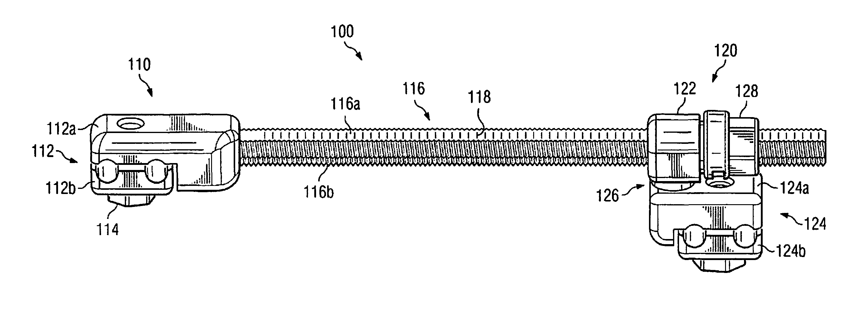
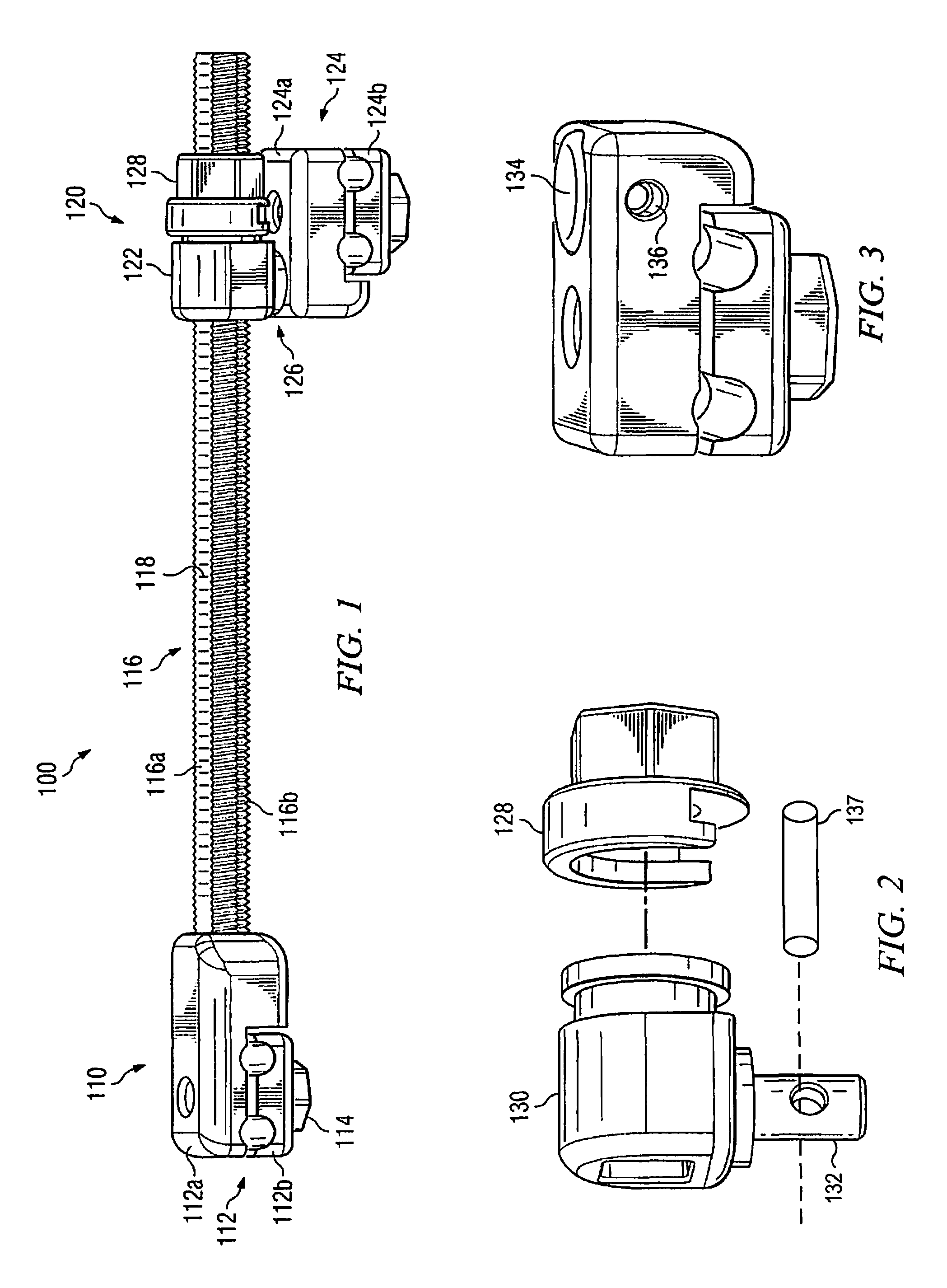
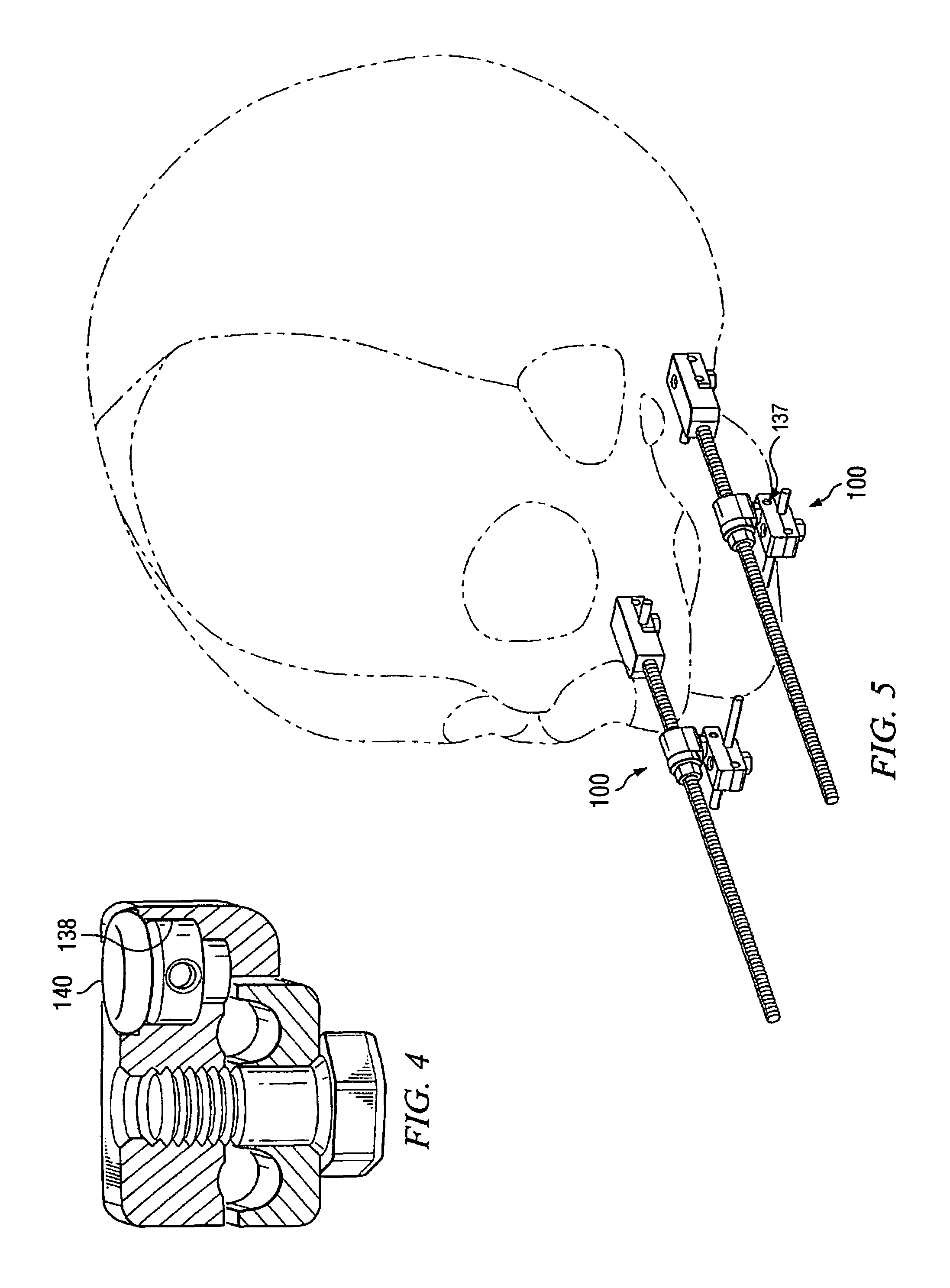
[0014]FIG. 1 illustrates an example embodiment of a mandibular distraction system 100. Mandibular distraction system 100 includes a posterior pin clamp assembly 110 rigidly coupled to one end of a rod 116 and an anterior pin clamp assembly 120 moveably coupled to rod 116 such that pin clamp assembly 120 may be adjustably positioned along the length of rod 116. As used herein, the terms anterior and posterior are used for the sake of explanatory simplicity to denote particular components of mandibular distraction system 100 with reference to an example situation wherein mandibular distraction system 100 is mounted on a mandible—the anterior portions being those closest to the point of the chin and the posterior portions being those closest to the mandibular joint. One of ordinary skill in the art will recognize that reference terms (e.g., anterior and posterior) are not meant to be limitive with respect to the placement of the components, nor are they meant to restrict the relative p...


PUM


Abstract

The present disclosure provides for a system for mandibular distraction which includes a rod and a first pin clamp assembly coupled adjacent a first end of the rod. Furthermore, the first pin clamp assembly includes a first clamp. The system further includes a second pin clamp assembly which includes an advancement mechanism that moveably couples the second pin clamp assembly to the rod and a second clamp. Furthermore, a swivel joint is disposed between the advancement mechanism and the second clamp whereby the second clamp is enabled to rotate relative to the advancement mechanism.

Description

TECHNICAL FIELD OF THE INVENTION[0001]The present invention relates to a device for manipulation of facial bones, and more particularly, the invention relates to a method and system for mandibular osteodistraction.BACKGROUND OF THE INVENTION[0002]Bones sometimes develop at different rates, leaving some bones disproportionately shorter than other bones. Alternatively, injury may leave a bone shorter than its original length. Such a condition may lead to difficulties in a patient's movement. For instance, a small jaw may cause difficulties in chewing or breathing (e.g., obstructive sleep apnea). Moreover, deformations are often psychologically distressing to the patient, especially when the deformations occur in craniofacial bones.[0003]One procedure for lengthening bones is referred to as osteodistraction. According to an osteodistraction procedure, an abnormally short bone is cut into two segments. The two segments are secured to a brace that permits the segments to be drawn apart. ...

Claims


Application Information

Patent Timeline
Patent Type & Authority Patents(United States)
IPC IPC(8): A61B17/56A61B17/68A61B17/60A61B17/66A61B17/02
CPCA61B17/66A61B17/68A61B17/663A61B17/60A61B17/56A61B17/025
Inventor GORDON, CHRISTOPHER BURNSIDEMOCANU, VIOREL
Owner OSTEOMED
Learn More