Input apparatus, control apparatus, and control method for input apparatus

a control apparatus and input technology, applied in the field of input apparatus, control apparatus, input apparatus control method, can solve the problems of more delicate power consumption control than the desktop wireless mouse, difficult to suppress the entire mouse power consumption, and also so as to achieve delicate power consumption control, prolong the battery life, and reduce the effect of power consumption

Inactive Publication Date: 2015-03-17
SONY CORP
View PDF8 Cites 6 Cited by
  • Summary
  • Abstract
  • Description
  • Claims
  • Application Information

AI Technical Summary

Benefits of technology

[0010]However, because the 3-dimensional mouse as described in Patent Document 1 is equipped with many devices that consume more electric power than in a desktop wireless mouse, it has been difficult to suppress power consumption of the entire mouse and also prolong a battery life. An infrared sensor of the desktop wireless mouse only needs to detect values when the mouse is moving, but the acceleration sensor and the angular velocity sensor of the 3-dimensional mouse need to constantly detect values. Moreover, a relatively-large current flows into those sensors, and hence more delicate power consumption control than the desktop wireless mouse is desirable.

Problems solved by technology

However, because the 3-dimensional mouse as described in Patent Document 1 is equipped with many devices that consume more electric power than in a desktop wireless mouse, it has been difficult to suppress power consumption of the entire mouse and also prolong a battery life.
Moreover, a relatively-large current flows into those sensors, and hence more delicate power consumption control than the desktop wireless mouse is desirable.
The inventors of the present invention have found a new problem that since the number of sensors becomes large in the pointing device that is operated in the air as described in Patent Document 1, electric power consumed increases when trying to use it wirelessly.

Method used


Image

  • Input apparatus, control apparatus, and control method for input apparatus
  • Input apparatus, control apparatus, and control method for input apparatus
  • Input apparatus, control apparatus, and control method for input apparatus

Examples


example

[0146]Hereinafter, a specific example of mode shifts of the input apparatus 1 and the control apparatus 40 will be described.

[0147]FIG. 11 are diagrams showing a case where the operation mode of the input apparatus 1 is changed by the mode change command 300 and the mode change command 400 from the control apparatus 40. FIG. 12 is a sequence diagram in this case.

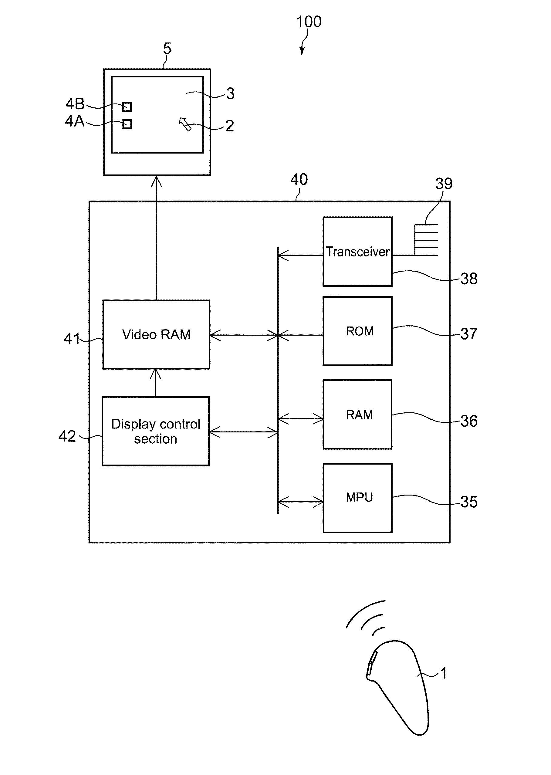
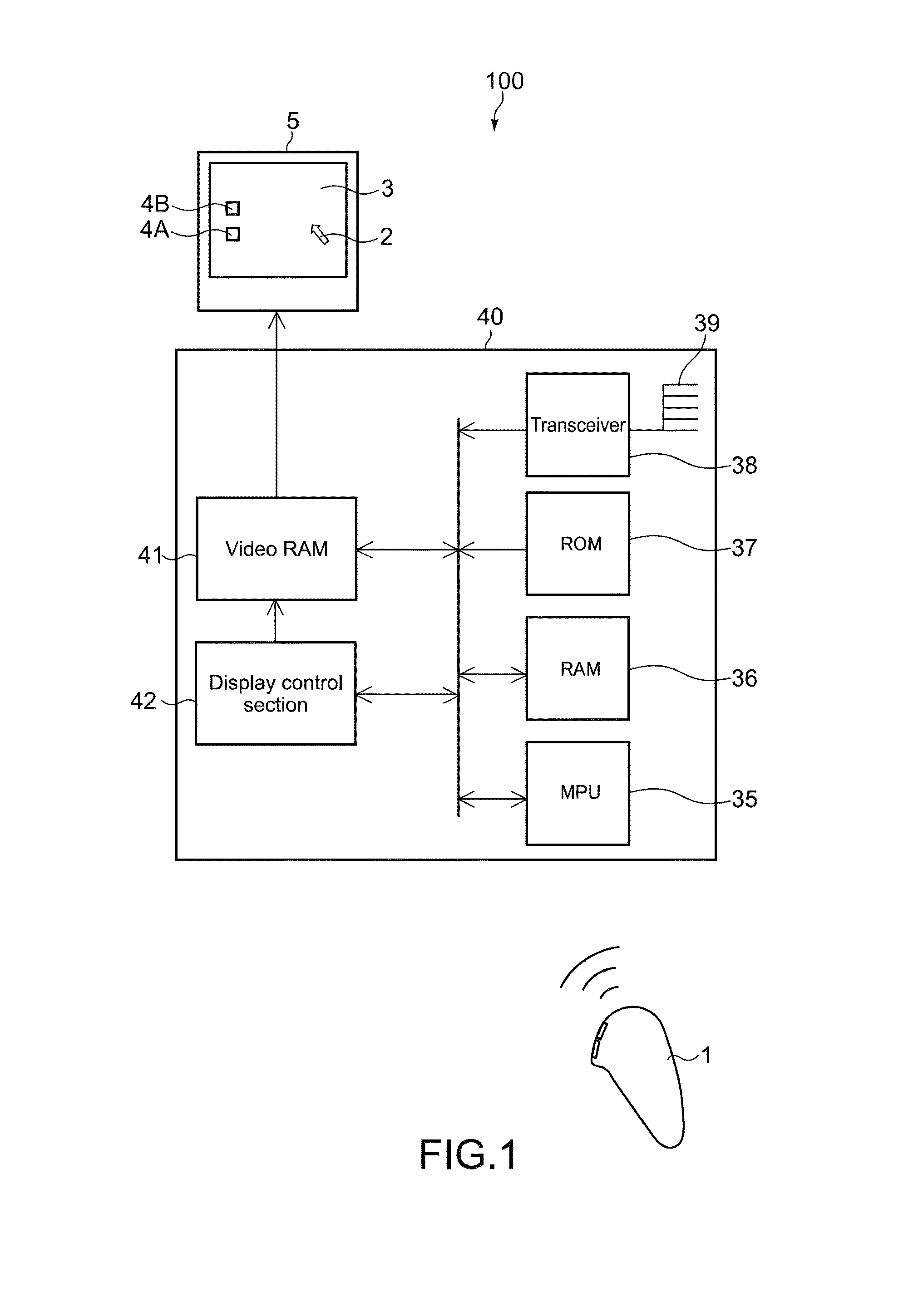
[0148]When power of the input apparatus 1, the control apparatus 40, and the display apparatus 5 is turned on by the user, the input apparatus 1 and the control apparatus 40 shift to, for example, the non-free mode as shown in FIG. 10. At this time, as shown in FIG. 11A, a viewing program screen is displayed on a screen 3A of the display apparatus 5, for example.

[0149]When an operation for displaying a non-free GUI screen 3B (e.g., button operation) is made by the user, for example, the input apparatus 1 transmits a command C1 corresponding to the operation to the control apparatus 40 as shown in FIG. 12. The control apparat...


PUM


Abstract

An input apparatus capable of transmitting a signal corresponding to an operation of a user to a control apparatus capable of switching display among a plurality of display screens, includes a first detection section, a second detection section, and a mode switch section. The first detection section detects analog information on a movement of the input apparatus made by the user. The second detection section detects digital information input by the user. The mode switch section makes a switch between a first mode for transmitting to the control apparatus a first signal that is based on the analog information detected by the first detection means and a second mode for transmitting to the control apparatus a second signal that is based on the digital information detected by the second detection means, in association with the display screen displayed on the control apparatus.

Description

BACKGROUND OF THE INVENTION[0001]1. Field of the Invention[0002]The present invention relates to an input apparatus such as a 3-dimensional operation pointing device, a 3-dimensional operation remote controller, and a cellular phone, a control apparatus capable of receiving a signal from the input apparatus, and a control method for an input apparatus.[0003]2. Description of the Related Art[0004]Pointing devices, particularly a mouse and a touchpad, are used as controllers for GUIs (Graphical User Interfaces) widely used in PCs (Personal Computers).[0005]Not just as HIs (Human Interfaces) of PCs of the related art, the GUIs are now starting to be used as interfaces for AV equipment used in living rooms with televisions as image media. Examples of the HI of this type include a cross media bar, an EPG, an IP-TV, and Windows Media Center.[0006]As the HIs currently in wide use, there are remote controllers with arrow keys as extensions of remote controllers for AV equipment of the relat...

Claims


Application Information

Patent Timeline
Patent Type & Authority Patents(United States)
IPC IPC(8): G06F3/033G06F3/0346G06F3/0354
CPCG06F3/0346G06F3/0383G06F2203/0384G06F2203/0383
Inventor KABASAWA, HIDETOSHIYAMAMOTO, KAZUYUKIMAMIYA, TOSHIOFUCHIGAMI, YOSHIYUKI
Owner SONY CORP
Why Eureka
Try Eureka